Dobinsons Springs and Suspension
Fitting Guide
1.
Remove the number plate.
2.
Remove the bumper bar or factory bullbar if
fitted.
3.
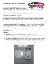
Install the bullbar mounting brackets and
cross brace as per the diagram on page 3.
4.
Install all bolts and tighten. The bolts at the
top rear section of the outer brackets may
need to be drilled through the chassis and
installed.
5.
Carefully un-wrap the bulbar taking care not
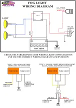
to scratch it especially on the top loops.
Reinstall the number plate to the bullbar as it
is easier now. If installing driving lights to the
bullbar it is easiest to install now.
6.
If mounting a winch see steps 7 – 16.
7.
The winch mounts directly to the rear of the
bullbar. If fitting a Dobinsons Winch the
clutch handle will be on the left hand side of
the vehicle, with the wire spooling from the
bottom of the winch.
8.
See the Installation section of your Dobinsons
4x4 Winch manual for specific detailed fitting
instructions. For a brief overview see the
following steps.
9.
This will require the clutch handle and gear-
box housing to be rotated forward 2 bolt
holes to allow easy access through the bulbar
holes. See instructions in winch user manual.
10.
Determine where the winch control box will
be located and mount the control box; it is
easiest to mount to the top of the bar.
11.
Sit the winch behind the bullbar and un wind
about a metre of cable and pass through the
fairlead hole in the bullbar.
12.
With the fairlead sitting in front of the bullbar
pass the winch cable through the roller
fairlead. This may require removing a circlip
from the fairlead and re installing once the
cable is passed through.
13.
With help from another person, hold the
fairlead in position at the front of the bullbar
and the winch in position at the rear of the
bullbar and bolt the winch and fairlead to the
bullbar using the lower bolts.
14.
Install the top winch mounting bolts.
15.
Tighten the winch bolts and ensure the winch
bolts are not too long and tighten correctly.
16.
Wire the winch up as per the winch
instruction manual and bolt the winch to the
mounting bracket. Route the wires and
connect to battery and also route the
breather hose.
17.
Wire up the lights. Using a multimeter or test
light first locate the earth wire, parker positive
and indicator positive wires from the wiring
on the back of the original vehicle lights on
each side.
18.
Unclip the wiring from the indicator/parker
lights. Check that the wiring will be long
enough to reach the new bullbar
indicator/parker lights and extend if required.
Using the diagram at the end of this manual,
join the corresponding wires to original
vehicle wires located in the previous step. The
wires can be joined by either using good
quality snap lock crimp connectors or by
soldering. Ensure the connection is secure and
is sufficiently insulated.
19.
If fitting a bullbar with fog lights, the fog lights
can be connected using the original vehicle
fog light wires if fitted. If required, cut the old
fog light wiring plugs off and cut the new fog
light wiring plugs and join. If the vehicle is not
fitted with OEM fog lights the wiring loom
supplied can be used. Follow the wiring
diagram at the end of this manual.
20.
For a better finish the lower outer sections of
the front wheel arch panel can be painted
satin black.
21.
With help, fit the bulbar into position and
install nuts and bolts supplied. The
adjustment stopper bolts on the front of the
bullbar (item 3) touch against the front of the
chassis. Depending on the exact alignment of
the bar these may need to be cut a little
shorter.


