background image

28

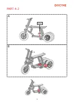
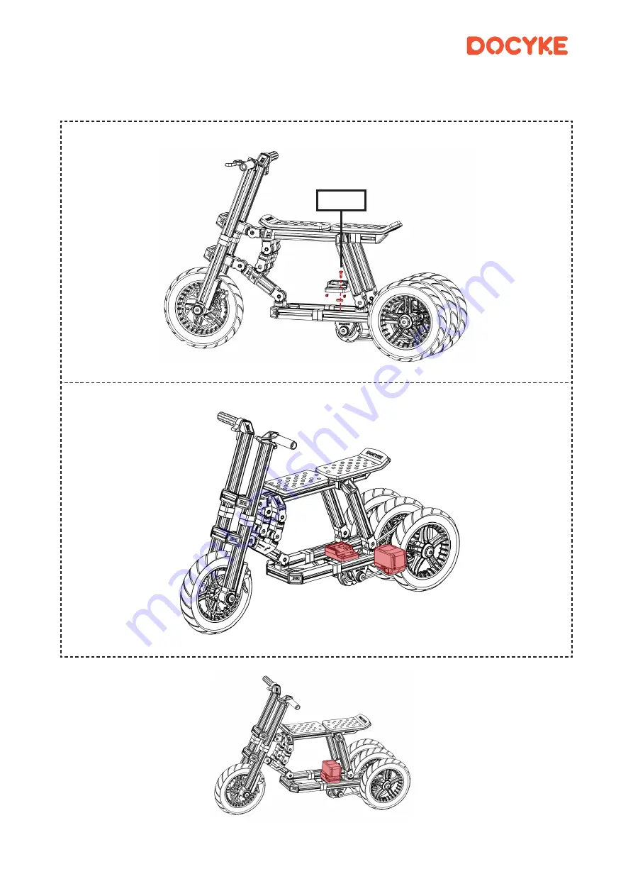
PART 4-2

A

B

M8x20

Summary of Contents for GK-06

Page 1: ...1 Motor power 400W Battery capacity 18V 6Ah Charging time 2 3h Time to bulid 6 20 hours Max load 50kg Net weight 30kg Using time 1hour GO KART KIT MFDUSPOJD 1SPHSBNNJOH JU 685 3 4 2 06 K...

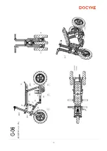
Page 2: ...1 1 2 4 5 32 33 Contents Warning GK 06 GK 06 assembly drawing GK 06 GK 06 diagram...

Page 3: ...assure that young riders are able to safely and responsibly use this product We recommends that you review and reinforce the information in this manual periodically with younger riders inspect and mai...

Page 4: ...e that all small parts and plastic bags are accounted for and kept out of the reach of children 6 Dirt 1eaves and other debris can damage shrink expand or weaken docyke parts Keep your ride in a dry e...

Page 5: ...objects when it is not used in case shorting the battery terminal together may cause burns or fire 4 Do not open the battery and charger Danger of short circuiting Protect the battery against heat e...

Page 6: ...5 GK 06 1 3 2 4 PART PART PART PART...

Page 7: ...6 1 PART PART 1 1 PART 1 2...

Page 8: ...ks are some of the smallest parts but they also some of the most important Putting them in the right place is a key of the product PART 1 1 M8x25 M6 2 280mm A B C M8x25 M6x35 2 240mm Tighten the two s...

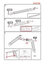
Page 9: ...8 D E F X2 X2 M8x20 2 Pay attention to the up and down direction of parts M8x25 M8...

Page 10: ...uired to use different lengths in different locations so be sure to follow the instruction manual and use the Hex wrench handle to tighten the screws prevent them coming loose M8x25 H M6x14 4 M6x20 2...

Page 11: ...10 C X2 A B PART 1 2 M8x20 20mm M8x25 M8 M8x20 2 80mm Tighten the bolts with full force to prevent them coming loose...

Page 12: ...11 D E F X2 X2 140mm 220mm M8x60 M8 M8x20...

Page 13: ...12 2 PART PART 2 1 PART 2 2...

Page 14: ...13 PART 2 1 M8x25 M6 2 360mm A B C M8x25 M6x35 2 60mm Tighten the two screws after connection Tighten the bolts with full force to prevent them coming loose...

Page 15: ...14 D E F X2 10 5 Each mark is 10 and the maximum accuracy is 5 half mark 2 As shown in the figure assemble 2 components M8x60 M8x20 2 M8x20 2 200mm 20...

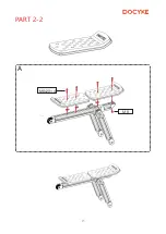
Page 16: ...15 PART 2 2 A M8x20 4 M8...

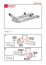
Page 17: ...16 3 PART PART 3 1 M8x25 M6 2 320mm A B M8x25 M6x35 2 140mm...

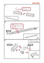
Page 18: ...17 C Tighten the two screws after connection D E X2 M8x20 2 M8x20 2 120mm Pay attention to the up and down direction of parts...

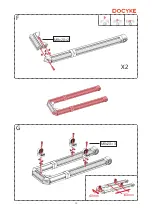
Page 19: ...18 F M8x20 2 X2 G M8x20 3 40mm 140mm...

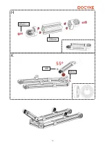
Page 20: ...19 H M8x20 2 120mm K M8x32 M8 55...

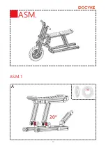
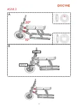
Page 21: ...20 A ASM ASM 1 20...

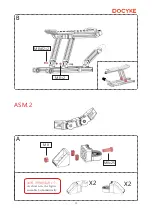
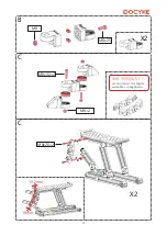
Page 22: ...21 M8x32 2 M8 2 B ASM 2 A 2 As shown in the figure assemble 2 symmetrically M8 M8x25 X2 X2...

Page 23: ...22 C B C X2 X2 2 As shown in the figure assemble 2 components M8 M8x25 M8x32 2 M8 2 M8x20 2 13 2mm 16mm...

Page 24: ...23 A B ASM 3 M8x32 2 M8 2 15 20...

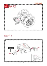
Page 25: ...24 PART 4 1 4 PART A M8x20 2...

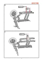
Page 26: ...25 B C M8x20 2 M8x20 2...

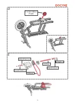
Page 27: ...26 D E M8x20 2 22x 32xh2 2 22x 32xh5 2 222mm 936mm T34 Belt Wheel Fixed 8x 30xh2 2...

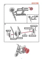
Page 28: ...27 F G M8x20 2 8x 30xh2 2 22X 32xh40 2 22x 32xh10 5 418mm 22x 32xh5 22x 32xh2...

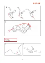
Page 29: ...28 PART 4 2 A B M8x20...

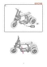
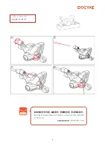
Page 30: ...29 C M8x20 X2...

Page 31: ...30 Fix the cable...

Page 32: ...31 P9 H Applied at P9 H If you have any questions better ideas or join our team welcome to contact us do docyke com...

Page 33: ...32...

Page 34: ...33...

Page 35: ...34...

Reviews: