background image

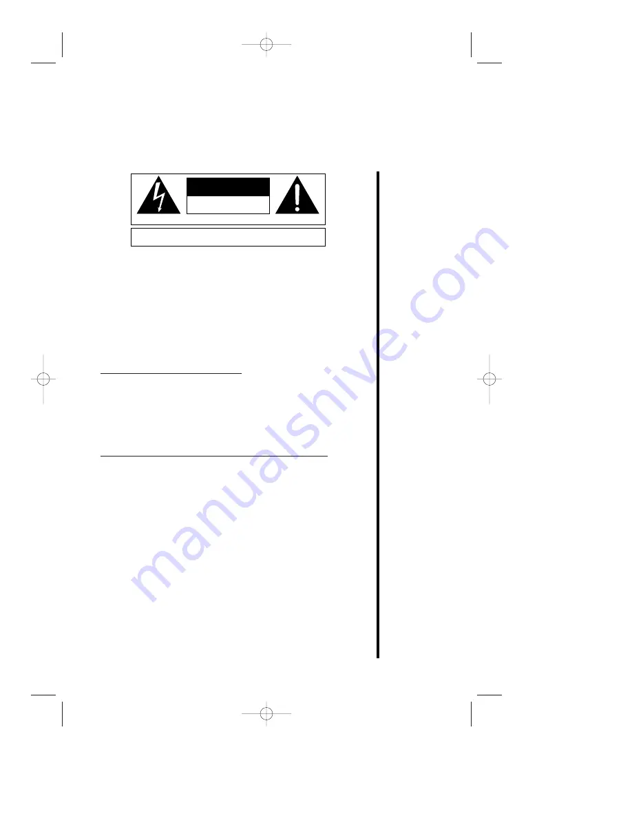
The symbols shown above are internationally accepted symbols that warn of
potential hazards with electrical products.  The lightning flash with arrowpoint in an
equilateral triangle means that there are dangerous voltages present within the
unit.  The exclamation point in an equilateral triangle indicates that it is necessary
for the user to refer to the owner’s manual.

These symbols warn that there are no user serviceable parts inside the unit.  Do
not open the unit.  Do not attempt to service the unit yourself.  Refer all servicing
to qualified personnel.  Opening the chassis for any reason will void the manufac-
turer’s warranty.  Do not get the unit wet.  If liquid is spilled on the unit, shut it off
immediately and take it to a dealer for service.  Disconnect the unit during storms
to prevent damage.

U.K. MAINS PLUG WARNING

A moulded mains plug that has been cut off from the cord is unsafe.  Discard the
mains plug at a suitable disposal facility.  NEVER UNDER ANY CIRCUMSTANCES
SHOULD YOU INSERT A DAMAGED OR CUT MAINS PLUG INTO A 13 AMP
POWER SOCKET.  
Do not use the mains plug without the fuse cover in place.
Replacement fuse covers can be obtained from your local retailer.  Replacement
fuses are 13 amps and MUST be ASTA approved to BS1362.

SAFETY INSTRUCTIONS (EUROPEAN)

NOTICE FOR CUSTOMERS IF YOUR UNIT IS EQUIPPED WITH A POWER
CORD.

WARNING: THIS APPLIANCE MUST BE EARTHED.

The cores in the mains lead are colored in accordance with the following code:

GREEN and YELLOW - Earth        BLUE - Neutral        BROWN - Live

As colors of the cores in the mains lead of this appliance may not correspond with
the colored markings identifying the terminals in your plug, proceed as follows:

• The core which is colored green and yellow must be connected to the ter-

minal in the plug marked with the letter E, or with the earth symbol, or col-
ored green, or green and yellow.

• The core which is colored blue must be connected to the terminal marked

N or colored black.

• The core which is colored brown must be connected to the terminal marked

L or colored red.

C A U T I O N

A T T E N T I O N :


R I S Q U E   D E   C H O C   E L E C T R I Q U E   -   N E   P A S   O U V R I R

W A R N I N G :


T O   R E D U C E   T H E   R I S K   O F   F I R E   O R   E L E C T R I C

S H O C K   D O   N O T   E X P O S E   T H I S   E Q U I P M E N T   T O   R A I N   O R   M O I S T U R E

R I S K   O F   E L E C T R I C   S H O C K

D O   N O T   O P E N

1

R410 Manual  6/8/99  10:41 AM  Page 1

Summary of Contents for 410 SERIES II

Page 1: ... A 13 AMP POWER SOCKET Do not use the mains plug without the fuse cover in place Replacement fuse covers can be obtained from your local retailer Replacement fuses are 13 amps and MUST be ASTA approved to BS1362 SAFETY INSTRUCTIONS EUROPEAN NOTICE FOR CUSTOMERS IF YOUR UNIT IS EQUIPPED WITH A POWER CORD WARNING THIS APPLIANCE MUST BE EARTHED The cores in the mains lead are colored in accordance wi...

Page 2: ...ool etc Care should be taken so that objects do not fall and liquids are not spilled into the enclosure through openings POWER SOURCES The appliance should be connected to a power supply only of the type described in the operating instructions or as marked on the appliance GROUNDING OR POLARIZATION Precautions should be taken so that the grounding or polarization means of an appliance is not defea...

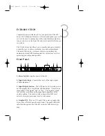
Page 3: ...he limiter This allows a comparison of the signal wet or dry The input level and low cut filter are always in the signal path regardless of the switch position The meter switch connects the LED level meter to the input post input level or the output 4 Graphic EQ This is a 15 band 2 3rds octave graphic EQ It provides 12dB of gain for each band The peak LED indi cates that the signal out of the EQ s...

Page 4: ...R Limiting behaves as a mild compressor with a soft knee at low threshold settings and a hard knee lim iter at higher threshold settings This allows the limiter to func tion as a mild compressor or as a limiter for speaker protection The fast slow speed switch affects both the attack and release time This gives enough variety for most situations The gain reduction meter displays the amount of gain...

Page 5: ...g connections 5 Balanced Input Accepts a male XLR plug see section on installation for wiring connections Maximum allowable input is 21dBu Input impedance for the balanced connection is 102Ω 6 Balanced Unbalanced Input Accepts a 1 4 tip ring sleeve balanced phone plug or a 1 4 unbalanced tip sleeve plug see section on installation for wiring connections Maximum allowable input is 21dBu Input imped...

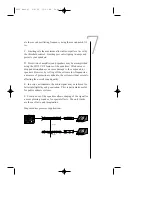
Page 6: ...een installed and adjusted an optional 801 security panel may be installed to keep unauthorized persons from tampering with the settings APPLICATIONS A Using the 410 in conjunction with a real time analyzer such as DOD s RTA Series II a calibrated microphone and pink noise generator the audio system may be tuned to make the overall audio spectrum response of the sound system and the room environme...

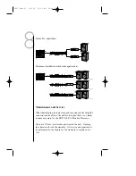
Page 7: ...nitor Feed Power Amp Power Amp R410 Series II Floor Monitor Floor Monitor Mixer 410 seriesII METER 3 6 12 3 6 12 25 0 3 6 12 3 6 12 0 40 63 100 160 250 400 630 1K 1 6K 2 5K 4K 6 3K 10K 16K p a monitor speaker processor LOW CUT IN OUT INPUT x10 Hz x10 Hz FREQUENCY Hz 130 70 220 40 400 dB 10 6 3 1 GAIN REDUCTION dBu IN OUT LEVEL 10 0 10 PEAK PEAK FREQUENCY Hz 630 200 2k 1 1k 360 14 2 THRESHOLD dBu 6...

Page 8: ...OUT INPUT x10 Hz x10 Hz FREQUENCY Hz 130 70 220 40 400 dB 10 6 3 1 GAIN REDUCTION dBu IN OUT LEVEL 10 0 10 PEAK PEAK FREQUENCY Hz 630 200 2k 1 1k 360 14 2 THRESHOLD dBu 6 10 22 dB 6 6 GAIN dB 0 12 12 SPEED FAST SLOW FREQ 40Hz 80Hz METER INPUT OUTPUT 0 dB 8 16 24 CUT 0 dB 8 16 24 CUT INPUT OUTPUT GRAPHIC EQUALIZER NOTCH 1 NOTCH 2 LIMITER LOW CUT R410 Series II 410 seriesII METER 3 6 12 3 6 12 25 0 ...

Page 9: ... to a period of one year The company shall not be responsible for any con sequential damage as a result of the products use in any circuit or assembly Proof of date of purchase is considered to be the burden of the consumer DOD reserves the right to make changes in design or make improvements upon this product without incurring any obligation to install the same on PRODUCTS PREVIOUSLY MANUFACTURED...

Page 10: ...nced Maximum Input Level 21dBu ref 0 775 VRMS Output Impedance 51Ω unbalanced 102Ω bal anced Maximum Output Level 21dBu Thru Output Hard wired to input Graphic EQ Band Separation 2 3 Octave Notch Filter Q 40 Limiter Attack Time Slow 18ms Fast 2ms Limiter Release Time Slow 180ms Fast 20ms Low Cut Filter Slope 12dB Octave R410 Manual 6 8 99 10 41 AM Page 10 ...

Page 11: ... N I I I I C C C C S S S S C C C C O O O O R R R R P P P P O O O O R R R R A A A A T T T T I I I I O O O O N N N N O O O OW W W WN N N NE E E ER R R R S S S S M M M MA A A AN N N NU U U UA A A AL L L L 4 4 4 41 1 1 10 0 0 0 S S S SE E E ER R R RI I I IE E E ES S S S I I I II I I I R410 Manual 6 8 99 10 41 AM Page 11 ...

Page 12: ...NATIONAL DISTRIBUTION 3 OVERLOOK DR UNIT 4 AMHERST NEW HAMPSHIRE 03031 U S A FAX 603 672 4246 DOD IS A REGISTERED TRADEMARK OF DOD ELECTRONICS 1995 DOD ELECTRONICS CORPORATION PRINTED IN U S A 7 95 MANUFACTURED IN THE U S A DOD 410 18 2101 B R410 Manual 6 8 99 10 41 AM Page 12 ...

Reviews: