1
WARNING: Because of the possible danger to person(s)
or property from accidents which may result from the
improper use of products, it is important that correct
procedures be followed. Products must be used in
accordance with the engineering information specified
in the catalog. Proper installation, maintenance and
operation procedures must be observed. The instructions
in the instruction manuals must be followed. Inspections
should be made as necessary to assure safe operation
under prevailing conditions. Proper guards and other
suitable safety devices or procedures as may be
desirable or as may be specified in safety codes should
be provided, and are neither provided by Dodge nor are
the responsibility of Dodge. This unit and its associated
equipment must be installed, adjusted and maintained by
qualified personnel who are familiar with the construction
and operation of all equipment in the system and the
potential hazards involved. When risk to persons or
property may be involved, a holding device must be an
integral part of the driven equipment beyond the speed
reducer output shaft.
WARNING: To ensure the drive is not unexpectedly
started, turn off and lock-out or tag power source before
proceeding. Failure to observe these precautions could
result in bodily injury.
WARNING: All products over 25 kg (55 lbs) are noted on the
shipping package. Proper lifting practices are required for
these products.
Parts Replacement Manual For HYDROIL
®
TORQUE-ARM
®
Speed
Reducers Taper Bushed For Char-Lynn H, S, T and 2000 Series
6B Spline Motors
SIZES: HXT325C, HXT425C/HXT415C, HXT525C
These instructions must be read thoroughly before installation or operation. This instruction manual was accurate at the time of
printing. Please see
dodgeindustrail.com
for updated instruction manuals.
These instructions must be read thoroughly before installing or operating this product.
NOTE: The reducer is compatible with the Dodge Ability
Smart Sensor, that can be installed in the adapter plug
labeled “smart sensor”. The plug and sensor can be moved
to different locations as required by mounting position.
REDUCER INSTALLATION
1. On sizes HXT3B, HXT4B, and HXT5C, replace the plastic
plug that protects the threaded hole in the reducer housing
with the eyebolt supplied with the reducer.
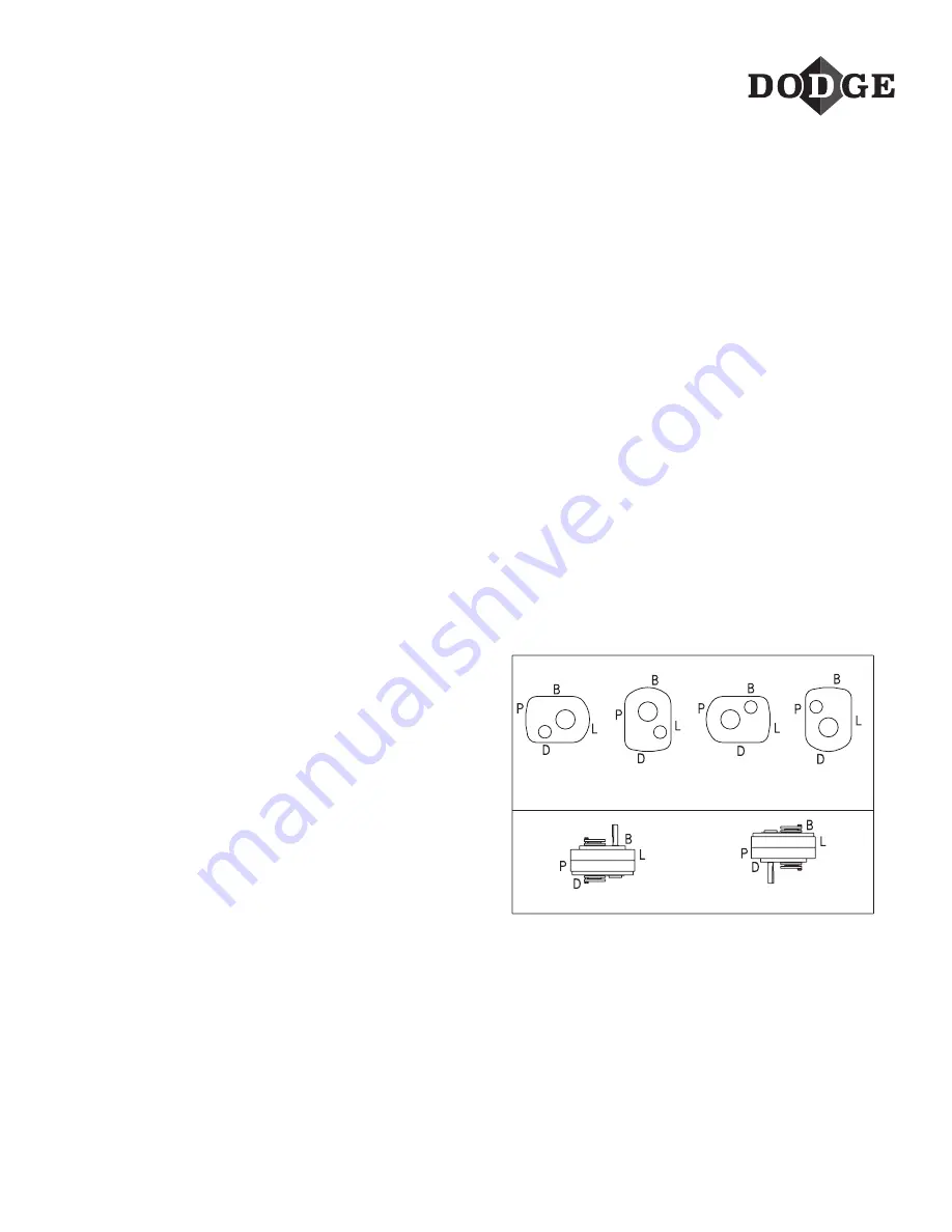
2. Determine the running position of the reducer (see Fig.
1). Note that the reducer is supplied with either 6 plugs;
4 around the sides for horizontal installations and 1 on
each face for vertical installations. These plugs must be
arranged relative to the running positions as follows:
Horizontal Installations
– Install the magnetic drain plug
in the hole closest to the bottom of the reducer. Install vent
plug in topmost hole. Of the 2 remaining plugs on the sides
of the reducer, the lowest one is the minimum oil level plug.
HORIZONAL APPLICATIONS
VERTICAL MOUNT
Position A
Position B
Position C
Position D
Position E
Position F
B = Breather
D = Drain
L = Level
P = Plug
Figure 1 - Mounting Positions
The running position of the reducer in a horizontal
application is not limited to the four positions shown in
Figure 1. However, if running position is over 20º either way
from sketches, the oil level plug cannot be safely used to
check the oil level, unless during the checking the torque
arm is disconnected and the reducer is swung to within
20º in positions “B” and “D” or 5º in positions “A” and “C”
of the positions shown in Figure 1. Because of the many
possible positions of the reducer, it may be necessary or
desirable to make special adaptations using the lubrication
fitting holes furnished along with other standard pipe
fittings, stand pipes and oil level gages as required.
Summary of Contents for HYDROIL TORQUE-ARM HXT325C
Page 11: ...11...

