


13
MN1617
WARNING: The Dodge Quantis MSM and its connected
equipment and accessories must be guarded. Rotating
parts such as couplings, pulleys, fans and unused shaft
extensions must be permanently guarded by the user
against accidental contact with personnel and their
clothing. The surface temperature of the Dodge Quantis
MSM enclosure may reach temperatures which can cause
discomfort or injury to personnel accidentally coming into
contact with hot surfaces. The user should provide guards to
prevent accidental contact with hot surfaces. Guards must
be sufficiently rigid to maintain adequate guarding in normal
service.
WARNING: Threaded hardware used to mount the Dodge
Quantis MSM Unit must be SAE Grade 5 or Metric Class 8.8
or better. DO NOT USE HARDWARE OF A LOWER GRADE.
MAINTENANCE
Check oil levels and oil quality regularly. Change oil at the
intervals specified in the Lubricants section of this document.
Check alignments of drive components regularly. Check chain
and belt tensions and hardware tightness periodically too.
Assembly/Disassembly Motorized Shaft
Mount (MSM) Reducer
Please follow the instructions outlined below when assembling
and disassembling this unit. Failure to follow the instructions as
outlined may result in damage to the gear unit or to the machine’s
drive shaft. For ease of assembly, it is recommended that the
machine’s drive shaft be chamfered. DO NOT HAMMER THE
GEARBOX SHAFT ONTO THE MACHINE’S DRIVE SHAFT.
The machine’s drive shaft should be produced in accordance
with the dimensions shown on the accompanying Table 5 or 6.
Assembly
All shaft mounted gearboxes are furnished with A) Retaining
Ring B) Keeper plate C) Retaining Bolt D) Spring Washer E) Dust
Cap and Anti-Seize as shown in the finished assembly, Figure
5. Apply the anti-seize onto the customer shaft before installing
reducer onto the shaft. The gearbox is pulled onto the shaft by
means of a threaded rod and nut assembly as shown in Figure
4 below. The threaded rod and spacer are not supplied. The
threaded rod (M) is specified in Table 5 or 6. After the gearbox
has been pulled completely onto the machine shaft firmly against
the machine shaft’s backing shoulder, it must be locked in place
with the retaining bolt tightened to the tightening torque shown in
Table 4.
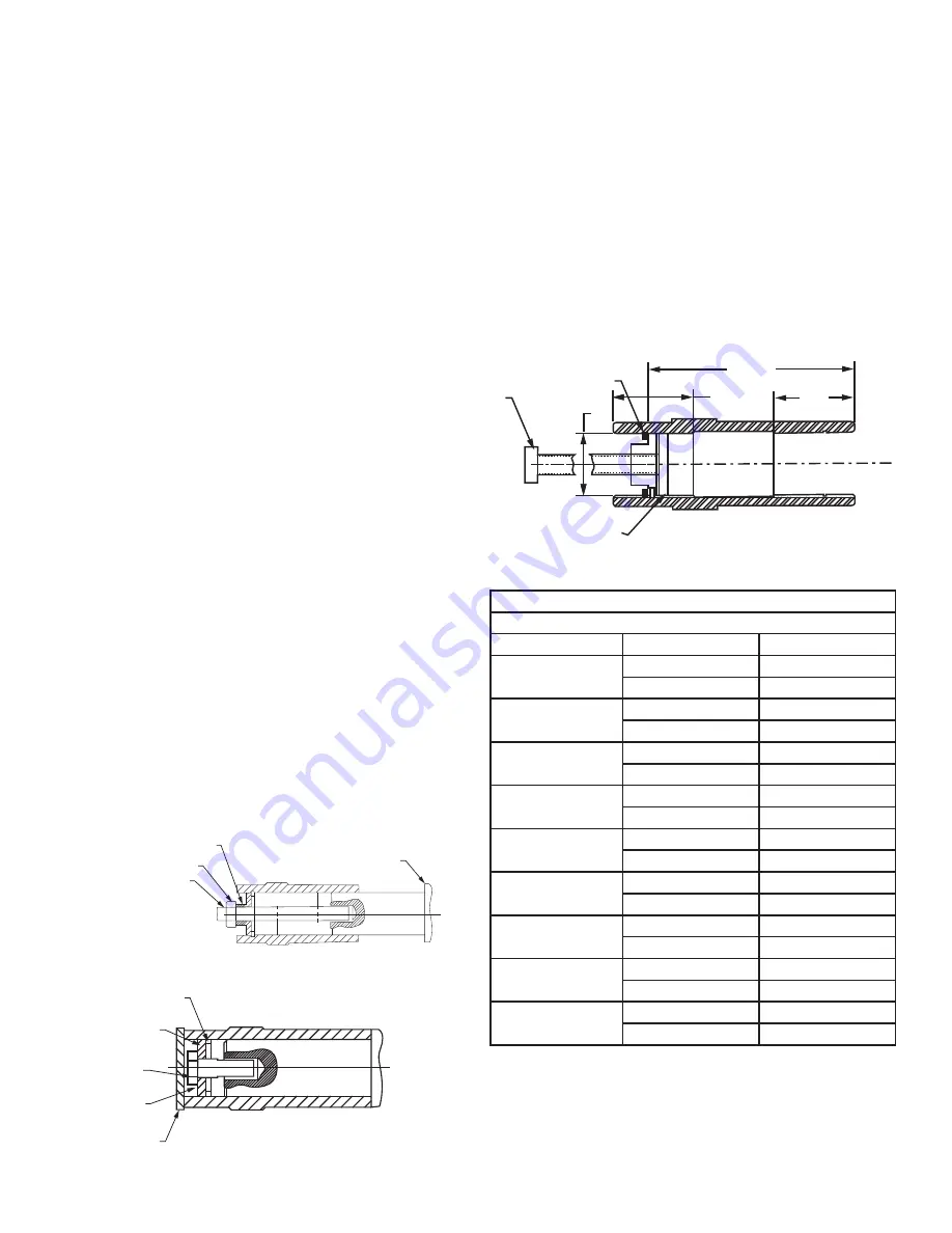
Disassembly
Prior to disassembly, the dust cap, retaining bolt, spring washer,
keeper plate and retaining ring must be removed. For ease of
disassembly, it is recommended that the following tools be made
and used as described: The round keyed nut (A) is inserted into
the free space between the retaining ring in the gear unit’s hollow
shaft and the end of the machine’s drive shaft. The removal bolt
(B) is screwed into the nut (A) which presses a disk (C) against
the machine’s drive shaft. The resulting force pushes the gearbox
off of the machine’s drive shaft. Reference Figure 6 for the
disassembly arrangement.
NOTE: The retaining bolt supplied with the gear unit cannot
be used for this purpose and must be replaced with the
bolt specified in Table 5 or 6. The round keyed nut and disk
should be made from 1045 steel and removal bolt should be
a minimum of SAE Grade 5.
Table 4–Tightening Torques for Retaining Bolt
Recommended Tightening Torque for Retaining Bolt
Unit Size
Bolt Thread Size (M)
Torque
MW38
3/8–16
248 in-lb
M10
16 N-m
MW48
3/8–16
248 in-lb
M12
28 N-m
MW58
5/8-11
611 in-lb
M16
69 N-m
MW68
5/8–11
611 in-lb
M16
69 N-m
MW88
¾–10
1221 in-lb
M16
69 N-m
MW108
¾–10
1221 in-lb
M20
138 N-m
MW128
¾–10
1221 in-lb
M20
138 N-m
MW148
¾–10
1221 in-lb
M20
138 N-m
MW168
1–8
2098 in-lb
M24
237 N-m
SPACER
NUT
THREADED ROD
Machine’s Drive Shaft
Backing Shoulder
Figure 4 – Threaded Rod and Nut Assembly
B
C
D
E
A
Figure 5 – Finished Assembly
B
A
U
C
M4
M4
VG
Figure 6 – Disassembly Arrangement


