background image

Basic Voice Commands

The basic Voice Commands below can be
given at any point while using your Uconnect
system.

Push the VR button

. After the beep, say:

• “

Cancel

” to stop a current voice session

• “

Help

” to hear a list of suggested Voice

Commands

• “

Repeat

” to listen to the system prompts

again

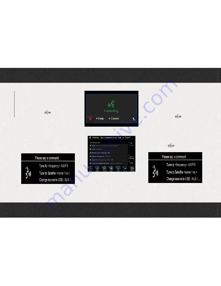
Notice the visual cues that inform you of your
voice recognition system’s status. Cues ap-
pear on the top of the touchscreen.

Radio

Use your voice to quickly get to the AM, FM or
SiriusXM Satellite Radio stations you would
like to hear. (Subscription or included
SiriusXM Satellite Radio trial required.)

Push the VR button

. After the beep,

say:

• “

Tune to

ninety-five-point-five FM”

• “

Tune to Satellite Channel

Hits 1”

TIP:

At any time, if you are not sure of what to

say or want to learn a Voice Command, push
the VR button

and say “

Help

.” The

system provides you with a list of commands.

Uconnect 3.0 Radio Visual Cues

Uconnect 3 With 5–inch Display Radio

Visual Cues

Uconnect 4C/4C NAV With 8.4–inch

Display Radio Visual Cues

Uconnect 3.0

MUL

TIMEDIA

248

Summary of Contents for RAM 1500 2019

Page 1: ...int or download a copy of the Owner s Manual Navigation Uconnect manuals and the limited warranties provided by FCA US LLC for your vehicle by visiting WWW MOPAR COM U S or WWW OWNERS MOPAR CA Canada...

Page 2: ...US LLC for your vehicle by visiting www mopar com U S or www owners mopar ca Canada Click on the applicable link in the Popular Topics area of the www mopar com U S or www owners mopar ca Canada homep...

Page 3: ...and maintain the vehicle including emergency information When it comes to service remember that your authorized dealer knows your vehicle best has factory trained technicians and genuine MOPAR parts a...

Page 4: ...Getting To Know Your Instrument Panel for further infor mation on the symbols used in your vehicle VAN CONVERSIONS CAMPERS The New Vehicle Limited Warranty does not apply to body modifications or spec...

Page 5: ...F CONTENTS GETTING TO KNOW YOUR VEHICLE GETTING TO KNOW YOUR INSTRUMENT PANEL SAFETY STARTING AND OPERATING IN CASE OF EMERGENCY SERVICING AND MAINTENANCE TECHNICAL SPECIFICATIONS MULTIMEDIA CUSTOMER...

Page 6: ...adlight Switch 29 Headlights 29 Daytime Running Lights DRL If Equipped 29 High Low Beam Switch 30 Automatic High Beam Headlamp Control If Equipped 30 Flash To Pass 31 Automatic Headlights If Equipped...

Page 7: ...orting Passengers 119 Exhaust Gas 119 Safety Checks You Should Make Inside The Vehicle 120 Periodic Safety Checks You Should Make Outside The Vehicle 121 STARTING AND OPERATING STARTING THE ENGINE GAS...

Page 8: ...HICLE 183 Two Wheel Drive Models 184 Four Wheel Drive Models 184 Emergency Tow Hooks If Equipped 185 ENHANCED ACCIDENT RESPONSE SYSTEM EARS 185 EVENT DATA RECORDER EDR 185 SERVICING AND MAINTENANCE SC...

Page 9: ...NE 237 Uconnect Phone Bluetooth Hands Free Calling 237 Pairing Wirelessly Connecting Your Mobile Phone To The Uconnect System 239 Common Phone Commands Examples 243 Mute Or Unmute Microphone During Ca...

Page 10: ...er Glove Compartment 2 Instrument Cluster Display Controls 7 Upper Switch Panel 12 Lower Glove Compartment 3 Instrument Cluster 8 Uconnect System 13 Lower Switch Panel 4 Speed Controls 9 Climate Contr...

Page 11: ...INTERIOR Interior 1 Door Handles 3 Seats 2 Door Locks Window Switches 4 Front Storage Bin 9...

Page 12: ...ument panel and rotate to the de sired position It also contains the key fob and an emergency key which stores in the rear of the key fob The emergency key allows for entry into the vehicle should the...

Page 13: ...pull the key out with your other hand NOTE When using the emergency key to gain access to your vehicle be aware that the security alarm may be triggered Put the nose side side opposite of the emergenc...

Page 14: ...this vehicle This device complies with Part 15 of the FCC Rules and with Industry Canada license exempt RSS standard s Operation is sub ject to the following two conditions 1 This device may not cause...

Page 15: ...your foot applied on the brake pedal and push to operate the ignition switch REMOTE START IF EQUIPPED How To Use Remote Start All of the following conditions must be met before the engine will remote...

Page 16: ...vice may not cause harmful inter ference and 2 This device must accept any interference received including interference that may cause undesired operation NOTE Changes or modifications not expressly a...

Page 17: ...sive Entry Unlock Door Handle with a valid key fob within 5 ft 1 5 m of the passive entry door handle If equipped refer to Keyless Enter N Go Passive Entry in Getting To Know Your Vehicle for further...

Page 18: ...pushing the passive entry key fob lock unlock buttons if equipped The key fob may not be able to be detected by the vehicle passive entry system if it is located next to a mobile phone laptop or other...

Page 19: ...outside of the vehicle for any valid Passive Entry key fobs If one of the vehicle s Passive Entry key fobs is detected inside the vehicle and no other valid Passive Entry key fobs are detected outsid...

Page 20: ...p proved by the party responsible for compli ance could void the user s authority to oper ate the equipment Child Protection Door Lock To provide a safer environment for children riding in the rear se...

Page 21: ...a seat belt properly Driver Memory Seat If Equipped This feature allows the driver to store up to two different memory profiles for easy recall through a memory switch Each memory pro file contains d...

Page 22: ...s in Multimedia in the Owner s Manual for further information If your vehicle is not equipped with a touch screen you must select the Key Fob Linked To Memory feature through the instrument cluster di...

Page 23: ...en you remove the key fob from the igni tion or change the ignition to OFF for ve hicles equipped with Keyless Enter N Go When you remove the key fob from the ignition or change the ignition to OFF fo...

Page 24: ...Press the heated seat button a third time to turn the heating elements off When the HI level setting is selected the heater will provide a boosted heat level dur ing the first four minutes of operati...

Page 25: ...ion are small fans that draw the air from the passenger compartment and move air through fine perforations in the seat cover to help keep the driver and front passenger cooler in higher ambient temper...

Page 26: ...traint pull upward on the head restraint To lower the head re straint push the adjustment button located on the base of the head restraint and push downward on the head restraint NOTE Do not repositio...

Page 27: ...a location outside the occupant compartment ALL the head restraints MUST be rein stalled in the vehicle to properly protect the occupants Follow the re installation instructions above prior to operati...

Page 28: ...ated steering wheel has only one temperature setting Once the heated steering wheel has been turned on it will operate for an average of 80 minutes before automatically shutting off This time may vary...

Page 29: ...ls can be adjusted with the igni tion OFF The pedals cannot be adjusted when the vehicle is in REVERSE or when the Speed Control System is on The following mes sages will appear on vehicles equipped w...

Page 30: ...rs if the following occurs The mirrors are accidentally blocked while folding The mirrors are accidentally manually folded unfolded The mirrors come out of the unfolded posi tion The mirrors shake and...

Page 31: ...ht switch is on the parking lights taillights license plate light and instrument panel lights are also turned on To turn off the headlights rotate the headlight switch back to the O off position Dayti...

Page 32: ...the field of view will cause headlights to remain on longer closer to the vehicle Also dirt film and other obstructions on the windshield or camera lens will cause the system to func tion improperly...

Page 33: ...ith Automatic Headlights Only When this feature is active the headlights will turn on approximately 10 seconds after the wipers are turned on if the headlight switch is placed in the AUTO position In...

Page 34: ...is moved it would suggest that the indicator bulb is defective Cargo Light With Bed Lights If Equipped The cargo light and bed lights if equipped are turned on by pushing the cargo lights button loca...

Page 35: ...two to three cycles after the washer knob is released from this position If the washer knob is depressed while in the delay range the wiper will operate for several seconds after the washer knob is re...

Page 36: ...ucts containing wax or silicone may reduce Rain Sensing performance The Rain Sensing system has protection fea tures for the wiper blades and arms and will not operate under the following conditions L...

Page 37: ...Automatic Climate Controls With A Touchscreen Uconnect 3 Automatic Climate Controls 35...

Page 38: ...Uconnect 4C 4C NAV Automatic Climate Controls GETTING TO KNOW YOUR VEHICLE 36...

Page 39: ...Automatic Climate Control Knobs 37...

Page 40: ...circulation mode and outside air mode Recirculation can be used when outside conditions such as smoke odors dust or high humidity are present Recirculation can be used in all modes Recirculation may b...

Page 41: ...cator will illuminate when the rear window de froster is on The rear window defroster automatically turns off after ten minutes Uconnect 3 Uconnect 4C 4C NAV Driver and Passenger Temperature Up and Do...

Page 42: ...l knob on the faceplate or the buttons on the touch screen Faceplate The blower speed increases as you turn the blower control knob clockwise from the lowest blower setting The blower speed decreases...

Page 43: ...r Mode Air comes from the floor outlets A slight amount of air is directed through the defrost and side window demister out lets Mix Mode Mix Mode Air is directed through the floor defrost and side wi...

Page 44: ...maximum cool ing performance Press and release to toggle between MAX A C and the prior settings The button illuminates when MAX A C is on In MAX A C the blower level and mode posi tion can be adjuste...

Page 45: ...oster performance make sure the engine cooling system is functioning properly and the proper amount type and concentration of coolant is used Use of the Air Recircula tion mode during Winter months is...

Page 46: ...opening and closing switch on the front passenger door and the rear doors for passenger window controls The windows will operate when the ignition switch is turned to the ON RUN or ACC position and f...

Page 47: ...he window runs into any obstacle during the Auto Closure it will reverse direction and then go back down Remove the obstacle and use the window switch again to close the window Any impact due to rough...

Page 48: ...onsole between the courtesy reading lights WARNING Never leave children unattended in a vehicle or with access to an unlocked vehicle Never leave the key fob in or near the vehicle or in a location ac...

Page 49: ...n dition until the sunroof switch is pushed again Sunshade Operation The sunshade can be opened manually How ever the sunshade will open automatically as the sunroof opens NOTE The sunshade cannot be...

Page 50: ...ent and drop it Make sure that the hood is com pletely closed WARNING Be sure the hood is fully latched before driving your vehicle If the hood is not fully latched it could open when the vehicle is i...

Page 51: ...sure your hand held transmit ter is programmed to activate the device you are trying to program your HomeLink button to Ensure that your vehicle is parked outside of the garage before you begin progra...

Page 52: ...not have a rolling code These devices will also not have a LEARN or TRAIN button Programming HomeLink To A Garage Door Opener To program any of the HomeLink buttons to activate your garage door opener...

Page 53: ...repeat the final steps for the rolling code procedure Non Rolling Code Garage Door Opener Final Steps 1 Push and hold the programmed HomeLink button and observe the instru ment cluster display If the...

Page 54: ...he button proceed with Step 2 in Programming HomeLink To A Garage Door Opener and follow all re maining steps General Information The following regulatory statement applies to all Radio Frequency RF d...

Page 55: ...ehicle Limited Warranty The auxiliary power outlets can be found in the following locations Lower left and lower right in the center of the instrument panel if equipped with a column or a eight speed...

Page 56: ...in the vehicle must be driven a sufficient length of time to allow the generator to recharge the vehicle s bat tery Power Inverter If Equipped A 115 or 230 Volt 150 Watts Maximum outlet is located on...

Page 57: ...Body Builders Guide by accessing www rambodybuilder com and choosing the appropriate links PICKUP BOX The pickup box has many features designed for utility and convenience NOTE If you are installing a...

Page 58: ...ox The cargo storage bins provide watertight lockable illuminated storage for up to 150 lbs 68 kg of evenly distributed cargo CAUTION Failure to follow the following items could cause damage to the ve...

Page 59: ...ise to unlock Always return the key to the upright vertical position be fore removing the key from the push button CAUTION Ensure cargo bin lids are closed and latched before moving or driving vehicle...

Page 60: ...ront of the cargo tie down loops 4 Rotate the center handle horizontally to secure the side gates in the closed position 5 Lock the center handle using the vehicle key to secure the panel into place D...

Page 61: ...hould be in stowed or divider position with the tailgate closed When in use all handles are to be in the locked position Bed Rail Tie Down System CAUTION The maximum load per cleat should not exceed 2...

Page 62: ...the tailgate This will prevent damaging the connector and bracket when storing or reinstalling the tailgate Removing The Tailgate 1 Disconnect the wiring harness for the rear camera and or power locks...

Page 63: ...Tonneau Cover can be removed and rein stalled by using the locking clamps located underneath the Tonneau Cover Refer to the Owner s Manual for further information NOTE Be sure that the Tonneau Cover i...

Page 64: ...ormation you want and make selections and adjustments Instrument Cluster Display Controls The instrument cluster display features a driver interactive display that is located in the instrument cluster...

Page 65: ...ngine 2 Push and release the down arrow button to scroll downward through the main menu to Vehicle Info 3 Push and release the right arrow button to access the Vehicle Info screen then scroll up or do...

Page 66: ...ay never reach the conditions required to cleanse the filter to remove the trapped PM If this occurs the Exhaust Filter XX Full Safely Drive at Highway Speeds to Remedy message will be displayed in th...

Page 67: ...essage Engine Will Not Restart in XXXX mi DEF Low Refill Soon This message will display when DEF driving range is less than 500 miles DEF fluid top off is required with in the displayed mileage The me...

Page 68: ...ithin the displayed mileage The message will be displayed during vehicle start up with an updated distance mileage and it will be accompanied by a single chime Starting at 100 miles remaining range wi...

Page 69: ...m Units Easy Exit Seat ParkSense Key Off Power Delay Tilt Mirror In Reverse Commercial Settings Rain Sensing Wipers Park Assist Front Chime Volume Hill Start Assist Park Assist Rear Chime Volume Headl...

Page 70: ...RUN or ACC ON RUN position This light will illumi nate with a single chime when a fault with the air bag has been detected it will stay on until the fault is cleared If the light is either not on dur...

Page 71: ...ition NOTE This light shows only that the parking brake is applied It does not show the degree of brake application Vehicle Security Warning Light If Equipped This light will flash at a fast rate for...

Page 72: ...is light may turn on if the accelerator and brake pedals are pressed at the same time If the light continues to flash when the ve hicle is running immediate service is re quired and you may experience...

Page 73: ...ch as dry plants wood cardboard etc This could result in death or serious injury to the driver occupants or others CAUTION Prolonged driving with the Malfunction Indicator Light MIL on could cause dam...

Page 74: ...lacard or tire inflation pressure la bel If your vehicle has tires of a different size than the size indicated on the vehicle placard or tire inflation pressure label you should determine the proper t...

Page 75: ...Indicator Light When the fuel level reaches approximately 3 0 gal 11 0 L this light will turn on and remain on until fuel is added Anti Lock Brake ABS Warning Light This warning light monitors the Ant...

Page 76: ...vehicle is in the four wheel drive mode and the front and rear driveshafts are mechanically locked together forcing the front and rear wheels to rotate at the same speed 4WD Low Indicator Light If Eq...

Page 77: ...hen the left or right turn signal is activated the turn signal indicator will flash indepen dently and the corresponding exterior turn signal lamps will flash Turn signals can be activated when the mu...

Page 78: ...the high beam headlights are on With the low beams activated push the multifunc tion lever forward toward the front of the vehicle to turn on the high beams Pull the multifunction lever rearward towa...

Page 79: ...rols Authorized service technicians may need to access this information to assist with the diagnosis and service of your vehicle and emissions system WARNING ONLY an authorized service technician shou...

Page 80: ...rning TPMS Warning Light illumi nates you must increase the tire pressure to the recommended cold placard pressure in order for the TPMS Warning Light to turn off The system will automatically update...

Page 81: ...pressure gauge even if under inflation has not reached the level to trigger illumination of the TPMS Warning Light Seasonal temperature changes will affect tire pressure and the TPMS will monitor the...

Page 82: ...Warning Light will flash on and off for 75 seconds and then remain on solid The sys tem fault will also sound a chime In addi tion the instrument cluster will display a SERVICE TPM SYSTEM message for...

Page 83: ...e that has a pressure below the low pressure warning limit upon the next ignition switch cycle the TPMS Warning Light and a LOW TIRE message will re main ON and a chime will sound In addi tion the gra...

Page 84: ...u can take to minimize the risk of harm from a deploying air bag 1 Children 12 years old and under should always ride buckled up in the rear seat of a vehicle with a rear seat 2 A child who is not big...

Page 85: ...front seat passenger if equipped with outboard front passenger seat BeltAlert to buckle their seat belts The Belt Alert feature is active whenever the igni tion switch is in the START or ON RUN posi...

Page 86: ...belt webbing retractor will lock only during very sudden stops or collisions This feature allows the shoulder part of the seat belt to move freely with you under normal conditions However in a collis...

Page 87: ...seat belt into the buckle nearest you A seat belt that is too loose will not protect you properly In a sudden stop you could move too far forward increas ing the possibility of injury Wear your seat...

Page 88: ...the latch plate and pull on the lap belt A snug seat belt reduces the risk of sliding under the seat belt in a collision 5 Position the shoulder belt across the shoulder and chest with minimal if any...

Page 89: ...der belt anchorage in a lower position and if you are taller than average you will prefer the shoulder belt anchorage in a higher position After you release the anchorage button try to move it up or d...

Page 90: ...seat is folded The latch plate and regular latch plate can then be stored out of the way in the seat for added convenience to open up utilization of the storage areas behind the front seats when the s...

Page 91: ...rt the regular latch plate into the center red slot on the mini buckle The seat belt will automatically retract to its stowed position If necessary slide the latch plate down the webbing to allow the...

Page 92: ...death in a collision Only use the Seat Belt Extender when the lap belt is not long enough and only use in the recommended seating positions Re move and store the Seat Belt Extender when not needed Sea...

Page 93: ...ich is used to secure a child restraint system For additional information refer to Installing Child Restraints Using The Vehicle Seat Belt under the Child Restraints section of this manual The figure...

Page 94: ...straint in that vehicle How To Engage The Automatic Locking Mode 1 Buckle the combination lap and shoulder belt 2 Grasp the shoulder portion and pull down ward until the entire seat belt is extracted...

Page 95: ...to deployment The ORC turns on the Air Bag Warning Light in the instrument panel for approximately four to eight seconds for a self check when the ignition switch is first in the ON RUN position Afte...

Page 96: ...ury including death Air bags need room to WARNING inflate Sit back comfortably extending your arms to reach the steering wheel or instrument panel Never place a rear facing child restraint in front of...

Page 97: ...supplementing the seat belts Front air bags are not expected to reduce the risk of injury in rear side or rollover collisions The front air bags will not deploy in all frontal collisions including som...

Page 98: ...seam on the outboard side of the seatback s trim cover The inflating SAB deploys through the seat seam into the space between the occupant and the door The SAB moves at a very high speed and with such...

Page 99: ...essory items in your vehicle which could alter the roof Do not add an aftermarket sun roof to your vehicle Do not add roof racks that require permanent attach ments bolts or screws for installation WA...

Page 100: ...de Air Bags during deployment could cause you to be severely injured or killed Relying on the Side Air Bags alone could lead to more severe injuries in a colli sion The Side Air Bags work with your se...

Page 101: ...normally heal quickly However if you haven t healed significantly within a few days or if you have any blis tering see your doctor immediately As the air bags deflate you may see some smoke like parti...

Page 102: ...from the ignition switch to avoid draining the battery Carefully check the vehicle for fuel leaks in the engine com partment and on the ground near the engine compartment and fuel tank before resetti...

Page 103: ...Whether or not the driver and passenger safety belts were buckled fastened How far if at all the driver was depressing the accelerator and or brake pedal and How fast the vehicle was traveling These...

Page 104: ...s or call 1 888 327 4236 Canadian residents should refer to Transport Canada s website for additional information http www tc gc ca eng motorvehiclesafety safedrivers childsafety index 53 htm Summary...

Page 105: ...ut are still less than at least two years old Children should remain rear facing until they reach the highest weight or height allowed by their convertible child seat WARNING Never place a rear facing...

Page 106: ...move the vehicle seat forward or rearward because it can loosen the child restraint attachments Remove the child restraint before ad justing the vehicle seat position When the vehicle seat has been ad...

Page 107: ...esult in serious WARNING injury or death A child must always wear both the lap and shoulder portions of the seat belt correctly Recommendations For Attaching Child Restraints Restraint Type Combined W...

Page 108: ...s the seatback and one top tether anchorage located behind the seat ing position These anchorages are used to install LATCH equipped child seats without using the vehicle s seat belts Some seating pos...

Page 109: ...estraint is 65 lbs 29 5 kg Use the seat belt and tether anchor instead of the LATCH system once the combined weight is more than 65 lbs 29 5 kg Crew Cab 60 40 Split Bench LATCH Positions Lower Anchora...

Page 110: ...ating position Can two child restraints be attached using a common lower LATCH anchorage No Never share a LATCH anchorage with two or more child re straints If the center position does not have dedica...

Page 111: ...and seat cushion Locating The Upper Tether Anchorages Regular Cab models have tether strap anchorages behind the front center and right seats Quad Cab and Crew Cab models have tether strap anchorages...

Page 112: ...hat outboard position If a child seat in the center position blocks the outboard LATCH anchors or seat belt do not install a child seat in that outboard position WARNING Never use the same lower ancho...

Page 113: ...hild re straint route the seat belt through the child restraint belt path and then buckle it Do not lock the seat belt Remind all children in the vehicle that the seat belts are not toys and that they...

Page 114: ...w and the following sections for more information Lap Shoulder Belt Systems For Installing Child Restraints In This Vehicle Frequently Asked Questions About Installing Child Restraints With Seat Belts...

Page 115: ...itch able Automatic Locking Retractor ALR Child restraint systems are designed to be secured in vehicle seats by lap belts or the lap belt portion of a lap shoulder belt WARNING Improper installation...

Page 116: ...r anchor 9 Test that the child restraint is installed tightly by pulling back and forth on the child seat at the belt path It should not move more than 1 inch 25 4 mm in any direction Any seat belt sy...

Page 117: ...straint Repeat steps 4 to 6 above to complete the installation of the child restraint If the belt still cannot be tightened after you shorten the buckle disconnect the latch plate from the buckle turn...

Page 118: ...eploying Passenger Front Air Bag can cause death or serious injury to a child 12 years or younger including a child in a rear facing child restraint Quad or Crew Cab Trucks The top tether anchorages i...

Page 119: ...ts should be connected to the center tether strap loop This is the correct way to tether two outboard child seats Center Seat 1 Raise the head restraint and reach be tween the rear seat and rear glass...

Page 120: ...op but do not tighten the straps yet 3 Place a child restraint on the center rear seat Route the tether strap following the directions for the center seating position above 4 Attach the hook to the ou...

Page 121: ...or death It is extremely dangerous to ride in a cargo area inside or outside of a vehicle In a collision people riding in these areas are more likely to be seriously injured or killed Do not allow pe...

Page 122: ...as a bulb check when the ignition switch is first turned to ON RUN If the light is either not on during starting stays on or turns on while driving have the system inspected at an authorized dealer as...

Page 123: ...n the passenger s side floor area ALWAYS make sure objects cannot fall or slide into the driver s side floor area when the vehicle is moving Objects can become trapped under accelerator brake or clutc...

Page 124: ...lights on the instrument panel Door Latches Check for proper closing latching and lock ing Fluid Leaks Check area under the vehicle after overnight parking for fuel coolant oil or other fluid leaks A...

Page 125: ...s in hot weather Interior heat build up may cause serious injury or death Normal Starting Using ENGINE START STOP Button To Turn On The Engine Using The ENGINE START STOP Button 1 The transmission mus...

Page 126: ...nd time to place the ignition to the RUN mode 4 Push the ENGINE START STOP button a third time to return the ignition to the OFF mode AutoPark Rotary Shifter and 8 Speed Transmission Only AutoPark is...

Page 127: ...ParkSense graphic will be displayed in the instrument cluster causing the AutoPark Engaged Shift to P then Shift to Gear to not be seen In these cases the shifter must be returned to P to select desir...

Page 128: ...jured Children should be warned not to touch the parking brake brake pedal or the gear selector Do not leave the key fob in or near the vehicle or in a location accessible to children and do not leave...

Page 129: ...o start the vehicle If the vehicle fails to start the starter will disengage automati cally after 25 seconds 4 If you wish to stop the cranking of the engine prior to the engine starting push the butt...

Page 130: ...lowing pages occur It is a back up system and should not be relied upon as the primary method by which the driver shifts the vehicle into PARK The conditions under which AutoPark will engage are outli...

Page 131: ...he AutoPark Engaged Shift to P then Shift to Gear to not be seen In these cases the shifter must be returned to P to select desired gear If the driver shifts into PARK while moving the vehicle may Aut...

Page 132: ...ed option If your vehicle is not equipped heater cords are available from your authorized Mopar dealer A 12 Volt heater built into the fuel filter housing aids in preventing fuel gelling It is control...

Page 133: ...low 0 F 17 C the four flaps need to be closed A suitable cold weather cover is available from your Mopar dealer Stopping The Engine After full load operation idle the engine for a few minutes before s...

Page 134: ...st few thousand miles kilometers of operation This should be considered a nor mal part of the break in and not interpreted as a problem Please check your oil level with the engine oil indicator often...

Page 135: ...y fob from the vehicle and lock the vehicle Never use the PARK position as a sub stitute for the parking brake Always ap ply the parking brake fully when exiting the vehicle to guard against vehicle m...

Page 136: ...l must also be pressed to shift from NEUTRAL into DRIVE or REVERSE when the vehicle is stopped or moving at low speeds Eight Speed Automatic Transmission If Equipped The transmission is controlled usi...

Page 137: ...ome Mode is activated In this mode the transmission may operate only in certain gears or may not shift at all Vehicle performance may be severely degraded and the engine may stall In some situations t...

Page 138: ...able gears Tapping the GEAR switch on the steering wheel will activate ERS mode display the current gear in the instrument cluster and set that gear as the top available gear Once in ERS mode tapping...

Page 139: ...he transmission remains in direct gear regardless of which forward gear is selected PARK REVERSE and NEUTRAL will continue to operate The Malfunction Indicator Light MIL may be illuminated Limp Home M...

Page 140: ...t console shift or press and hold the ERS switch column shift until the gear limit display disappears from the instrument cluster WARNING Do not downshift for additional engine braking on a slippery s...

Page 141: ...road surfaces only 4WD LOW Four Wheel Drive Low Range This range provides low speed four wheel drive It maxi mizes torque to the front driveshaft forcing the front and rear wheels to rotate at the sa...

Page 142: ...e Switch which is located on the instrument panel This electronically shifted transfer case pro vides five mode positions Two Wheel Drive High Range 2WD Four Wheel Drive Automatic High Range 4WD AUTO...

Page 143: ...nditions the 4WD AUTO mode can be used In this mode the front axle is engaged but the vehicle s power is sent to the rear wheels Four wheel drive will be automatically engaged when the ve hicle senses...

Page 144: ...transfer case mode position see the information below 2WD Rear Wheel Drive High Range This range is for normal street and highway driving on dry hard surfaced roads 4WD LOCK Four Wheel Drive Lock High...

Page 145: ...is is accomplished by pushing the desired posi tion on the 4WD control switch Refer to Shifting Procedure in the Start ing And Operating section of your Owner s Manual for specific shifting instructio...

Page 146: ...OW Neutral NEUTRAL For additional information on the appropriate use of each transfer case mode position see the information below 2WD Rear Wheel Drive High Range This range is for normal street and h...

Page 147: ...l be automatically engaged when the ve hicle senses a loss of traction Because the front axle is engaged this mode will result in lower fuel economy than the 2WD mode When additional traction is requi...

Page 148: ...angerous You could acci dentally set the system or cause it to go faster than you want You could lose con trol and have an accident Always leave the system off when you are not using it To Set A Desir...

Page 149: ...can detect obstacles from approximately 18 inches 45 cm up to 79 inches 200 cm from the rear fascia bumper in the horizontal direction depend ing on the location type and orientation of the obstacle T...

Page 150: ...n button X to disable display of the camera image is made available when the vehicle is not in REVERSE gear When enabled active guide lines are overlaid on the image to illustrate the width of the veh...

Page 151: ...engine is running A fire may result if gasoline is pumped into a portable container that is inside of a vehicle You could be burned Always place gas containers on the ground while filling CAUTION Dam...

Page 152: ...or similar ingredients These can harm fuel system gas ket and diaphragm materials REFUELING THE VEHICLE 1500 DIESEL MODELS 1 Open the fuel filler door NOTE There is no fuel filler cap A flapper door...

Page 153: ...eet the very stringent diesel emissions standards required by the Environmental Protection Agency The purpose of the SCR system is to reduce levels of NOx oxides of nitrogen emitted from engines that...

Page 154: ...ltitude vehicle speed load etc will effect the amount of DEF that is used in your vehicle Another factor is that outside temperature can affect DEF consumption In cold con ditions 12 F 11 C and below...

Page 155: ...as diesel fuel fuel system additives gasoline or any other petroleum based product Even a very small amount of these less than 100 parts per million or less than 1 oz per 78 gallons 295 liters will co...

Page 156: ...of your new ve hicle drivetrain components the following guidelines are recommended CAUTION Do not tow a trailer at all during the first 500 miles 805 km the new vehicle is driven The engine axle or o...

Page 157: ...e braking and possible personal injury An electronically actuated trailer brake controller is required when towing a trailer with electronically actuated brakes When towing a trailer equipped with a h...

Page 158: ...nual brake control lever will display the GAIN setting for 10 seconds and the Trailer Brake Status Indicator Light will not be displayed If a fault is detected in the trailer wiring or the Integrated...

Page 159: ...ly increase the GAIN setting Repeat steps 8 and 9 until the GAIN setting is at a point just below trailer wheel lockup If towing a heavier trailer trailer wheel lockup may not be attainable even with...

Page 160: ...lability of controllers check with your trailer manufacturer or dealer Removal of the ITBM will cause errors and it may cause damage to the electrical sys tem and electronic modules of the vehicle See...

Page 161: ...ing the dolly manufacturer s instructions 5 Turn the ignition OFF and remove the key fob 6 Install a suitable clamping device de signed for towing to secure the front wheels in the straight position C...

Page 162: ...tic transmission is in PARK The park ing brake should always be applied when the driver is not in the vehicle CAUTION It is necessary to follow these steps to be certain that the transfer case is full...

Page 163: ...d no position indicator lights will be on or flashing A flashing NEUTRAL N position indicator light indicates that shift requirements have not been met Shifting Out Of NEUTRAL N Use the following proc...

Page 164: ...ore pushing the button to shift out of NEUTRAL N and must continue to be met until the shift has been completed If any of these requirements are not met before pushing the button or are no longer met...

Page 165: ...tery BULB REPLACEMENT Replacement Bulbs All of the inside bulbs are brass or glass wedge base Aluminum base bulbs are not approved Interior Bulbs Bulb Number Overhead Console Lamps TS 212 9 Dome Lamp...

Page 166: ...e for safety systems air bag system braking sys tem power unit systems engine sys tem transmission system or steering WARNING system blows contact an authorized dealer Power Distribution Center The Po...

Page 167: ...ler Exterior Lighting 2 If Equipped with Stop Start F11 30 Amp Pink Integrated Trailer Brake Module If Equipped F12 40 Amp Green Body Controller 3 Power Locks F13 40 Amp Green Blower Motor F14 40 Amp...

Page 168: ...are Fuse F33 20 Amp Blue Special Services Vehicle Only F34 30 Amp Pink Vehicle System Interface Module 2 If Equipped F35 30 Amp Pink Sunroof If Equipped F36 30 Amp Pink Rear Defroster If Equipped F37...

Page 169: ...F58 20 Amp Yellow Spare Fuse F59 10 Amp Red SCR Relay If Equipped F60 15 Amp Blue Underhood Lamp TCM F61 10 Amp Red 1500 LD Diesel Cummins Diesel PM Sensor If Equipped F62 10 Amp Red Air Conditioning...

Page 170: ...p Red Engine Control Module Electric Power Steering F79 15 Amp Blue Clearance Lights F80 10 Amp Red Universal Garage Door Opener Compass Anti Intrusion Mod ule F81 20 Amp Yellow Trailer Tow Right Turn...

Page 171: ...llow Power Outlets Instrument Panel Center Console Trunk CAUTION When installing the power distribution center cover it is important to ensure the cover is properly positioned and fully latched Failur...

Page 172: ...tires only The jack should not be used to lift the vehicle for service purposes The vehicle should be jacked on a firm level surface only Avoid ice or slippery areas Jack Location The jack and jack t...

Page 173: ...with enough cable slack to allow you to pull it out from under the vehicle 3 Pull the spare tire out from under the vehicle to gain access to the spare tire retainer 4 Lift the spare tire with one ha...

Page 174: ...he wheel diagonally opposite the wheel to be raised Apply the parking brake firmly and set the transmission in PARK Never start or run the engine with the vehicle on a jack Do not let anyone sit in th...

Page 175: ...front wheel place the scissor jack under the rear portion of the lower control arm as shown below 4x4 Series Trucks Front Jacking Location There is a jack location indicator on the rear portion of th...

Page 176: ...ning the lug nuts Push down on the wrench while at the end of the handle for in creased leverage Tighten the lug nuts in a star pattern until each nut has been tight ened twice For the correct lug nut...

Page 177: ...ved angle facing away from the vehicle Insert the extension tubes through the access hole between the lower tailgate and the top of the bum per and into the winch mechanism tube 4 Rotate the lug wrenc...

Page 178: ...arted using a set of jumper cables and a battery in another vehicle or by using a portable battery booster pack Jump starting can be dangerous if done improperly so please follow the procedures in thi...

Page 179: ...n gas which is flammable and explosive Keep open flames or sparks away from the battery 1 Apply the parking brake shift the auto matic transmission into PARK and turn the ignition OFF 2 Turn off the h...

Page 180: ...on the positive battery terminal The resulting electrical current will blow the fuse 6 Once the engine is started remove the jumper cables in the reverse sequence Disconnecting The Jumper Cables 1 Di...

Page 181: ...ar steam coming from under the hood do not open the hood until the radiator has had time to cool Never try to open a cooling system pressure cap when the radiator or coolant bottle is hot CAUTION Driv...

Page 182: ...access cover located to the right of the gear selector 4 Press and maintain firm pressure on the brake pedal 5 Insert the screwdriver or similar tool into the access hole and push and hold the overri...

Page 183: ...K such as a dead battery a Manual Park Release is available Follow these steps to activate the Manual Park Release 1 Firmly apply the parking brake 2 Using a small screwdriver or similar tool remove t...

Page 184: ...f accelerator pedal pressure that will maintain the rocking motion without spinning the wheels or racing the engine NOTE For trucks equipped with 8 speed automatic transmission Shifts between DRIVE an...

Page 185: ...mission overheating and failure It can also dam CAUTION age the tires Do not spin the wheels above 30 mph 48 km h while in gear no transmission shifting occurring TOWING A DISABLED VEHICLE This sectio...

Page 186: ...front wheels raised and the rear wheels on a towing dolly or when using a suitable steering wheel stabilizer to hold the front wheels in the straight position with the rear wheels raised and the front...

Page 187: ...ed off road Do not use tow hooks for tow truck hookup or highway towing You could damage your vehicle ENHANCED ACCIDENT RESPONSE SYSTEM EARS This vehicle is equipped with an Enhanced Accident Response...

Page 188: ...idle time is generally only a concern for fleet customers Severe Duty NOTE Change Engine Oil at 4 000 miles 6 500 km or 350 hours of engine run time if the vehicle is operated in a dusty and off road...

Page 189: ...urfaces If gear oil leakage is suspected check the fluid level If using your vehicle for police taxi fleet off road or frequent trailer towing change axle fluid X X X X X Inspect the brake linings rep...

Page 190: ...erval is mile age based only yearly intervals do not apply WARNING You can be badly injured working on or around a motor vehicle Do only service work for which you have the knowledge and the right equ...

Page 191: ...mation NOTE Under no circumstances should oil change intervals exceed 10 000 miles 16 000 km or twelve months whichever comes first Once A Month Or Before A Long Trip Check engine oil level Check wind...

Page 192: ...leakage is sus pected check the fluid level If using your vehicle for police taxi fleet off road or frequent trailer towing change the axle fluid X X X X X Inspect the brake linings parking brake fun...

Page 193: ...edge and the right equipment If you have any doubt about your ability to perform a service job take your vehicle to a com petent mechanic Failure to properly inspect and maintain your vehicle could re...

Page 194: ...Air Cleaner Filter 2 Engine Oil Dipstick 3 Engine Oil Fill 4 Brake Fluid Reservoir 5 Battery 6 Power Distribution Center Fuses 7 Washer Fluid Reservoir 8 Coolant Pressure Cap 9 Engine Coolant Reservo...

Page 195: ...ttery 2 Automatic Transmission Dipstick 6 Speed Trans Only 7 Power Distribution Center Fuses 3 Engine Oil Fill 8 Washer Fluid Reservoir 4 Engine Oil Dipstick 9 Coolant Pressure Cap 5 Brake Fluid Reser...

Page 196: ...Filter 6 Power Distribution Center PDC 2 Engine Oil Fill 7 Washer Fluid Reservoir 3 Brake Fluid Reservoir 8 Engine Coolant Reservoir 4 Aux Power Distribution Center Fuses 9 Engine Oil Dipstick 5 Batte...

Page 197: ...e Do not remove the air induction system air cleaner hoses etc unless such removal is necessary for repair or maintenance Make sure that no one is near the engine compartment before starting the vehic...

Page 198: ...government agency for advice on recycling programs and for where used fluids and filters can be properly disposed of in your area Drain the fuel water separator filter when the Water In Fuel Indicato...

Page 199: ...peration causes high fuel pressure High pressure fuel spray can cause serious injury or death 1 Add a substantial amount of fuel to the tank approximately 2 to 5 gal 8L to 19L 2 Press ignition switch...

Page 200: ...talyst to convert smog forming nitrogen oxides NOx into harmless nitrogen and wa ter vapor Refer to Fluids And Lubricants in Techni cal Specifications for further information HOISTING A conventional f...

Page 201: ...porary spare tires are designed for tem porary emergency use only Temporary high pressure compact spare tires have the letter T or S molded into the sidewall preced ing the size designation Example T1...

Page 202: ...ld only be achieved under specified operating conditions i e tire pressure vehicle loading road conditions and posted speed limits Load Identification Absence of the following load identification symb...

Page 203: ...ymbol certifies that the tire is in compliance with the U S Department of Transportation tire safety standards and is approved for highway use MA Code representing the tire manufacturing location two...

Page 204: ...asured in units of PSI pounds per square inch or kPa kilopascals Maximum Inflation Pressure The maximum inflation pressure is the maximum permissible cold tire inflation pres sure for this tire The ma...

Page 205: ...gned for your vehicle 4 Cold tire inflation pressures for the front rear and spare tires Loading The vehicle maximum load on the tire must not exceed the load carrying capacity of the tire on your veh...

Page 206: ...rmine the combined weight of luggage and cargo being loaded on the vehicle That weight may not safely exceed the available cargo and lug gage load capacity calculated in Step 4 6 If your vehicle will...

Page 207: ...205...

Page 208: ...affect vehicle handling and can fail sud denly resulting in loss of vehicle con trol Unequal tire pressures can cause steer ing problems You could lose control of your vehicle Unequal tire pressures...

Page 209: ...outdoor temperatures as tire pressures vary with temperature changes Tire pressures change by approximately 1 psi 7 kPa per 12 F 7 C of air temperature change Keep this in mind when checking tire pre...

Page 210: ...ode occurs when the tire inflation pressure is of or below 14 psi 96 kPa Once a Run Flat tire reaches the run flat mode it has limited driving capabili ties and needs to be replaced immediately A Run...

Page 211: ...highly recommended WARNING Tires and the spare tire should be replaced after six years regardless of the remaining tread Failure to follow this warning can result in sudden tire failure You could lose...

Page 212: ...ings approved for your vehicle Never use a tire with a smaller load index or capacity other than what was origi nally equipped on your vehicle Using a tire with a smaller load index could re sult in t...

Page 213: ...ing speeds loading and cold tire inflation pres sures While studded tires improve performance on ice skid and traction capability on wet or dry surfaces may be poorer than that of non studded tires So...

Page 214: ...lure to do so could result in spare tire failure and loss of vehicle con trol Collapsible Spare Tire If Equipped The collapsible spare is for temporary emer gency use only You can identify if your ve...

Page 215: ...es are for emergency use only Installation of this limited use spare tire affects vehicle handling With this tire do not drive more than the speed listed on the limited use spare wheel Keep inflated t...

Page 216: ...eaner These products may damage the wheel s protective finish Such damage is not covered by the New Vehicle Limited Warranty Only car wash soap Mopar Wheel Cleaner or equivalent is recom mended NOTE I...

Page 217: ...The Traction grades from highest to lowest are AA A B and C These grades represent the tire s ability to stop on wet pavement as measured under controlled conditions on speci fied government test surf...

Page 218: ...e is established for a tire that is prop erly inflated and not overloaded Ex cessive speed under inflation or excessive loading either separately or in combination can cause heat buildup and possible...

Page 219: ...ler recom mended lug nuts bolts and clean or remove any dirt or oil before tightening Inspect the wheel mounting surface prior to mounting the tire and remove any corrosion or loose particles Tighten...

Page 220: ...he requirements of FCA Material Standard MS 90032 13 7 Quarts 13 Liters 5 7L Engine We recommend you use Mopar Antifreeze Coolant 10 Year 150 000 Mile 240 000 km Formula that meets the requirements of...

Page 221: ...ved to FCA Material Standard MS 6395 may be used when SAE 5W 20 engine oil meeting MS 6395 is not available Engine Oil 5 7L Engine We recommend you use API Certified SAE 5W 20 Engine Oil meeting the r...

Page 222: ...This vehicle has not been designed for use with propylene glycol based engine coolant antifreeze Use of propylene glycol based engine coolant antifreeze is not recommended Chassis Component Fluid Lub...

Page 223: ...tra Low Sulfur Highway Diesel fuel 15 ppm Sulfur maximum and prohibits the use of Low Sulfur Highway Diesel fuel 500 ppm Sulfur maximum to avoid damage to the emissions control system For most year ro...

Page 224: ...iator This vehicle has not been designed for use with propylene glycol based engine coolant antifreeze Use of propylene glycol based engine coolant antifreeze is not recommended Chassis Component Flui...

Page 225: ...or U S residents and mopar ca for Canadian residents NOTE All parts are subject to availability CHROME Body Side Molding Tubular Side Steps Fuel Filler Door Cast Aluminum Wheels Front Air Deflector Gr...

Page 226: ...g safety related systems could be im paired or a loss of vehicle control could occur that may result in an accident involving serious injury or death ONLY insert media e g USB SD card or CD into your...

Page 227: ...INFO Button 3 A B C Button 4 Preset Buttons 5 BROWSE ENTER Button TUNE SCROLL Knob 6 SEEK Up Button 7 BACK Button 8 Play Pause MUTE Button 9 MENU Button 10 SEEK Down Button 11 AUDIO Button 12 ON OFF B...

Page 228: ...ings Treble Mid Bass Fade Balance Speed Ad justed Volume Loudness and AUX Offset Select the desired setting to adjust then push the ENTER BROWSE button Turn the TUNE SCROLL knob to adjust the setting...

Page 229: ...s without stopping USB Audio Jack AUX Manual Operation To select a specific audio source push the MEDIA button on the faceplate and select from the following modes USB iPod USB iPod Mode is entered by...

Page 230: ...tton 3 Phone Hang Up Button 4 A B C Button 5 BROWSE ENTER Button TUNE SCROLL Knob 6 SEEK Up Button 7 Play Pause MUTE Button 8 BACK Button 9 MENU Button 10 INFO Button 11 SEEK Down Button 12 ON OFF But...

Page 231: ...settings Treble Mid Bass Fade Balance Speed Ad justed Volume Loudness and AUX Offset Select the desired setting to adjust then push the ENTER BROWSE button Turn the TUNE SCROLL knob to adjust the set...

Page 232: ...hout stopping USB Audio Jack AUX Manual Operation To select a specific audio source push the MEDIA button on the faceplate and select from the following modes USB iPod USB iPod Mode is entered by eith...

Page 233: ...Glance Uconnect 3 With 5 inch Display Radio Buttons 1 RADIO Button 2 COMPASS Button 3 SETTINGS Button 4 MORE Functions Button 5 BROWSE ENTER Button TUNE SCROLL Knob 6 SCREEN OFF Button 7 MUTE Button 8...

Page 234: ...settings Equalizer Press the Equalizer button on the touch screen to adjust the Bass Mid and Treble Use the or button on the touchscreen to adjust the equalizer to your desired set tings Balance Fade...

Page 235: ...to the message using Voice Recognition by selecting or saying one of the 18 pre defined messages Here s How 1 Push the Voice Recognition VR or the Phone button and wait for the beep then say reply Uco...

Page 236: ...ta and System Information through buttons on the touchscreen Push the SETTINGS button Uconnect 3 With 5 inch Display or press the Apps button Uconnect 4C 4C NAV With 8 4 inch Display located near the...

Page 237: ...ens should not come into con tact with pointed or rigid objects which could damage its surface use a soft dry anti static cloth to clean and do not press Never use alcohol gas and derivatives to clean...

Page 238: ...ck browse and list the contents The battery charges when plugged into the USB port if supported by the specific de vice To route the USB cable out of the center console use the access cut out NOTE Whe...

Page 239: ...enu 1 Call Redial Hold 2 Mobile Phone Signal Strength 3 Currently Paired Mobile Phone 4 Mobile Phone Battery Life 5 Mute Microphone 6 Transfer To From Uconnect System 7 Uconnect Phone Settings Menu 8...

Page 240: ...ring 8 Text Messaging Menu 9 Direct Dial Pad 10 Contact Menu 11 Recent Call Log 12 Favorite Contacts 13 Mute Microphone 14 Decline Incoming Call 15 Answer Redial Hold 16 Mobile Phone Battery Life 17 T...

Page 241: ...ly Connecting Your Mobile Phone To The Uconnect System Mobile phone pairing is the process of estab lishing a wireless connection between a cel lular phone and the Uconnect system NOTE To use the Ucon...

Page 242: ...ed phones within range and will connect to the Uconnect system automatically when entering the vehicle Only one mobile phone and or one Bluetooth audio device can be connected to the Uconnect system a...

Page 243: ...your Bluetooth enabled iPhone 1 Press the Settings button 2 Select Bluetooth Ensure the Bluetooth feature is en abled Once enabled the mobile phone will begin to search for Bluetooth connections 3 Wh...

Page 244: ...bile phone audio device Bluetooth screen and the Uconnect system will reconnect to the Bluetooth device Pair Your Android Device To search for available devices on your Bluetooth enabled Android Devic...

Page 245: ...uetooth connection If this happens simply repeat the pairing pro cess However first make sure to delete the device from the list of phones on your Uconnect system Next be sure to remove Uconnect from...

Page 246: ...s different than the audio system Start a dialogue by pushing the VR button then say a command For example Help NOTE To access help push the Uconnect VR button if active on the steering wheel and say...

Page 247: ...e settings button on the mobile phone 2 Select Bluetooth Ensure Bluetooth is enabled and the mobile phone is paired to the Uconnect system 3 Select located under DEVICES next to Uconnect 4 Turn Show N...

Page 248: ...removing the battery if removable see your mobile phone s owner manual Delete pairing history in mobile phone and Uconnect system usually found in phone s Bluetooth connection settings Verify you are...

Page 249: ...d feature compatibility and to find phone pairing instructions 2 Reduce background noise Wind noise and passenger conversations are ex amples of noise that may impact recognition 3 Speak clearly at a...

Page 250: ...dio Use your voice to quickly get to the AM FM or SiriusXM Satellite Radio stations you would like to hear Subscription or included SiriusXM Satellite Radio trial required Push the VR button After the...

Page 251: ...tch your media source or choose an artist Change source to Bluetooth Change source to AUX Change source to USB Play artist Beethoven Play album Great est Hits Play song Moonlight Sonata Play genre Cla...

Page 252: ...commands Call John Smith Dial 123 456 7890 and follow the system prompts Redial call previous outgoing phone num ber Call back call previous incoming phone number TIP When providing a Voice Command pu...

Page 253: ...e could void the user s authority to oper ate the equipment Additional Information 2018 FCA US LLC All rights reserved Mopar and Uconnect are registered trademarks and Mopar Owner Connect is a tradema...

Page 254: ...o the general manager or owner of the authorized dealer They want to know if you need assistance If an authorized dealer is unable to resolve the concern you may contact the manufac turer s customer c...

Page 255: ...nufacturer s Service Contract National Customer Hotline at 1 800 521 9922 Ca nadian residents call 800 465 2001 Eng lish 800 387 9983 French The manufacturer will not stand behind any service contract...

Page 256: ...ou should contact the Customer Service Department imme diately Canadian customers who wish to report a safety defect to the Cana dian government should contact Transport Canada Motor Vehicle De fect I...

Page 257: ...omatic Temperature Control ATC 42 Automatic Transmission 134 Fluid Type 220 222 Automatic Transmission Limp Home Mode 135 Auxiliary Driving Systems 78 Auxiliary Switches 55 Axle Fluid 220 222 Battery...

Page 258: ...s Seat Back Tilt 19 Electrical Power Outlets 52 Electronically Shifted Transfer Case 139 140 142 144 Electronic Range Select ERS 136 137 Electronic Throttle Control Warning Light 70 Emergency In Case...

Page 259: ...tches Trailer Towing 154 Hoisting 198 HomeLink Garage Door Opener 49 Hood Prop 48 Hood Release 48 Ignition 12 Switch 12 In Case Of Emergency 163 Instrument Cluster Descriptions 75 Display 62 Engine Oi...

Page 260: ...nitor Tire Pressure System 78 Mopar Accessories 223 Multi Function Control Lever 29 New Vehicle Break In Period 132 Occupant Restraints 82 Oil Engine 219 221 Capacity 218 Filter 219 221 Pressure Warni...

Page 261: ...elt Reminder 68 Seat Belts 83 120 Adjustable Shoulder Belt 87 Adjustable Upper Shoulder Anchorage 87 Adjustable Upper Shoulder Belt Anchorage 87 Automatic Locking Retractor ALR 91 Child Restraints 101...

Page 262: ...203 Tire Markings 198 Tires 121 206 211 215 Aging Life Of Tires 209 Air Pressure 206 Compact Spare 212 General Information 206 211 High Speed 207 Inflation Pressure 207 Life Of Tires 209 Load Capacity...

Page 263: ...lity Rails Rear Cargo Area 59 Vehicle Loading 203 Vehicle Storage 43 Ventilated Seats 23 Voice Command 244 247 Commands 243 Voice Recognition System VR 243 244 247 Warning Lights Instrument Cluster De...

Page 264: ...262...

Page 265: ...263...

Page 266: ...264...

Page 267: ...US LLC for your vehicle by visiting www mopar com U S or www owners mopar ca Canada Click on the applicable link in the Popular Topics area of the www mopar com U S or www owners mopar ca Canada homep...

Page 268: ...int or download a copy of the Owner s Manual Navigation Uconnect manuals and the limited warranties provided by FCA US LLC for your vehicle by visiting WWW MOPAR COM U S or WWW OWNERS MOPAR CA Canada...

Reviews: