6
3931256/04/01/A - The right to make technical changes reserved!
Doepke
English
1- Table of Contents
Operating Instructions
DSU 1U Signal Converter
7. General Information
The DSU 1U Signal Converter is a component of the Dupline installation system and is
able to convert one voltage signal for transmission on the Dupline bus.
The input is suitable for AC voltages from 90 V to 265 V. There is no need to observe a
specific polarity. The signal converter activates the encoded channel when exceeding a
voltage difference of 90 VAC and disables the channel when the voltages drops below
60 VAC.
As it is supplied by the Dupline bus and due to the compact housing size of the device,
it is excellently suited for mounting e.g. in switch socket boxes or cavities.
8. Coding
With the DHK 1 hand encoder the input channel can be assigned any address between
A1 and P8 via the flat-plug connector on the front of the DSU 1U. The allocation of the
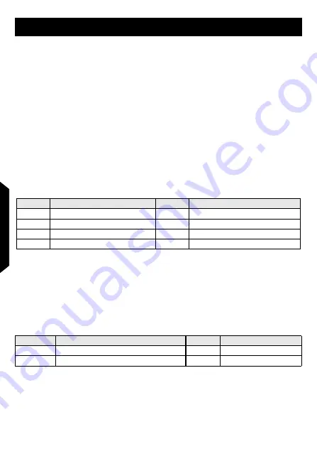
channels is as follows:
Channels which are not required should remain uncoded. Encoding the DSU 1U does
not require the Dupline signal. Although the coding is permanently retained, it may al-
ways be overwritten.
9. Putting into Service
Installation may only be carried out by an authorized technician. Observe the connection
diagram when installing. All leads to be connected must be dead. Connections between
the Dupline signal and earth potential will cause malfunctions and are not permissible. In
addition, check for the correct polarity of the Dupline signal.
The following table illustrates the connection configuration:
In order to meet the requirements for protective low voltage, VDE0100, Part 410, should
be observed and put into practice during installation.
10. Guarantee
All professionally installed, unaltered devices are covered by warranty during the statu-
Channel
Description
Channel
Description
1
Input Signal
5
Not assigned
2
Not assigned
6
Not assigned
3
Not assigned
7
Not assigned
4
Not assigned
8
Not assigned
Terminal
Description
Terminal
Description
White
Dupline signal con ()
Red
Input Signal
Black
Dupline signal conductor - (Dupline-)
Blue
Input Signal


