background image

Manual transducerized BMT series

DOC.60425-05/21

48

12. SAFETY

12.1 General dispositions

The instruction manual must be carefully stored in a known place and easily accessible to the potential users
of the product.

Warning

Read this manual and have each operator read it carefully before installing, using or repairing.

Make absolutely sure that the operator has fully understood the rules of use and the meaning of any symbols affixed to

the product.

Most accidents can be avoided by following the instruction manual.

These rules have been drafted with reference to the European Directives and their various amendments as well as

standard rules product.

In each case, respect and comply the National Safety Standards.

Do not remove or damage the labels and annotations affixed to the product,more particularly those imposed by the

law.

12.2 Work area

Keep your work area clean and well lit

. Cluttered benches and dark areas invite accidents.

Do not operate power tools in explosive atmospheres, such as in the presence of flammable liquids,
gases, or dust.

Power tools create sparks which may ignite the dust or fumes.

Keep bystanders, children, and visitors away while operating a power tool

. Distractions can cause you to

lose control.

12.3 Electrical safety

Grounded tools must be plugged into an outlet properly installed and grounded in accordance with all
codes and ordinances. Never remove the grounding prong or modify the plug in any way. Do not use any
plugs. Check with a qualified electrician if you are in doubt as to whether the outlet is properly grounded

.

If the tools should electrically malfunction or break down, grounding provides a low resistance path to carry
electricity away from the user.

Avoid body contact with grounded surface

ad pipes, radiators, ranges and refrigerators. There is an increased

risk of electric shock if your body is grounded.

Don't expose power tools to rain or wet conditions inside or outside

. Water entering a power tool will

increase the risk of electric shock

Do not abuse the cord. Never use the cord to carry the tools or pull the plug from an outlet

. Keep cord

away from heat, oil, sharp edges or moving parts.

Replace damaged cords immediately

. Damaged cords increase the risk of electric shock.

Summary of Contents for BMT Series

Page 1: ...Instruction manual WIRELESS DC TOOL Transducerized BMT series EN 60425 05 21 www dogassembly com ...

Page 2: ......

Page 3: ...HARGER SPECIFICATIONS 12 3 1 Battery 12 3 1 1 Specification 12 3 1 2 Battery pin configuration 12 3 1 3 Use 12 3 1 4 Battery safety rules 12 3 2 Battery charger 13 3 2 1 Specification 13 3 2 2 LED display 13 3 2 3 Charger Safety Rules 14 4 OPERATION 15 4 1 Screen display structure 15 4 2 Operation mode 15 4 3 Power Information Setting mode 16 4 3 1 Power information 16 4 3 2 Torque setting Speed s...

Page 4: ...MWARE UPGRADE 39 10 MODBUS COM PROTOCOL 41 11 MAINTENANCE 42 11 1 Maintenance 42 11 2 Trouble shooting 42 11 3 Error code 43 11 3 1 System errors 43 11 3 2 Fastening errors 44 11 4 Spare parts 45 11 5 Hotline 45 11 5 1 For any information regarding the use of the tool 45 11 5 2 For any information regarding troubleshooting 45 11 6 After sales Returns 46 11 6 1 Download the after sales return form ...

Page 5: ...DOC 60425 05 21 3 13 4 WEEE recycling and end of service life 52 13 4 1 Collection and recycling scheme 52 13 4 2 Collection points 52 14 APPENDICES 53 14 1 EC Declaration of Conformity 53 14 2 Parameter details and factory settings 53 ...

Page 6: ...Information Information to view in your customer area on the www doga fr web site Caution This warning statement indicates a low risk that may lead to minor or moderate injuries if not avoided Wear personal protection equipment This symbol indicates the need to wear protective gloves Warning This warning statement indicates a moderate risk that may lead to severe or fatal injuries if not avoided ...

Page 7: ...e required tool and or parts 1 2 Product reference Description Wireless Transducezized DC tool Type See hereunder 1 3 Product description BMT tool is a wireless transducerized torque and angle control screwdriver 1 4 Standard packing items BMT tool alone Pack BMT tool 2 batteries BMT tool X 1 X 1 Battery 25 2V 3A X2 USB A to mini USB B cable X 1 X 1 CE declaration of conformity X 1 X 1 Calibration...

Page 8: ... setting by torque Monitoring fastening quality and count of screw numbers Error information by code display Easy parameter setting and monitoring by ParaMonAIRT PC software Web Server Real time torque data and curve display Modbus protocol USB Wi Fi 2 4 GHz 5 GHz 1 6 System layout 1 6 1 Connection to PC 1 6 2 Connection to ParaMon Pro X for Multiple tool management WiFi WiFi LAN USB Setting data ...

Page 9: ...nces by USB or Wi Fi 2 2 Model specification Type Model Torque Nm Speed tr min Weight kg Standard Bit socket Pistol BMT3204 0 4 4 5 100 1800 1 0 Hex 1 4 BMT3206 0 6 6 5 100 1250 1 0 Hex 1 4 BMT3211 1 5 11 5 50 690 1 1 Hex 1 4 BMT3216 2 16 50 470 1 1 Hex 1 4 BMT3224 4 24 50 310 1 1 SQ 3 8 or Hex 1 4 Angle head BMTH3204 0 4 4 5 100 1800 1 4 SQ 3 8 or Hex 1 4 BMTH3206 0 8 6 5 100 1250 1 4 SQ 3 8 or H...

Page 10: ...afe speed not exceeding over torque by rotation inertia under the testing conditions described on the chart BMT3204 201 4 0 N m rpm 1800 0 4 100 BMT3206 168 6 5 N m rpm 1250 0 6 100 M3 rundown Hard joint 200Hz BMT3211 128 1 1 N m rpm 690 1 537 50 BMT3216 71 16 N m rpm 470 2 447 50 BMT3224 161 24 N m rpm 310 5 50 BMT3236 83 32 N m rpm 200 5 50 1031 1133 2 0 18 ...

Page 11: ...Manual transducerized BMT series DOC 60425 05 21 9 BMT3245 54 38 N m rpm 160 6 50 32 30 BMT3264 50 78 50 N m rpm 115 8 ...

Page 12: ...Manual transducerized BMT series DOC 60425 05 21 10 2 4 Screwdriver dimension and layout 2 4 1 Tool dimension 2 4 2 Layout ...

Page 13: ...complete then LED turn off Specification Barcode type 1D and 2D QR code Length Maximum read size is 32 character Traceability Barcode data is saved in memory with fastening data Max 65 000 and also merged to Modbus last tightening datas registers 3200 to 3229 Change preset automatically by barcode ParaMonAirT ParaMon Pro X can set barcode list Judged start end character can be set for each save ba...

Page 14: ...attery to water rain or condensation A battery short circuit can cause large current flow overheating possibly burns and even a break down Do not disassemble battery take it to a qualified service center when repair is required Incorrect reassembly may result in a risk of electric shock or fire Do not store the tool and battery in locations where the temperature may reach or exceed 50 C Do not inc...

Page 15: ...utput 25 2 VDC 4 0 A Fuse 250 VAC T 3 15 A Operating environment 0 40 C 15 80 RH without dew Full charging time 53 minutes Safety class Class II Weight 0 6 kg 3 2 2 LED display Battery inlet Press firmly AC power LED display LED display information Green blink Ready Red Charging Green Complete Red blink Battery overheat Yellow blink Charging Not possible ...

Page 16: ...njury and damage Before using battery charger read all instructions and cautionary marking on batteries chargers and product using batteries Do not allow anything to cover or clog the charger vents and cooling fan Only indoor use do not expose charger to rain or wet conditions Do not operate charger if it has been damaged in any way Do not disassemble take it to a qualified service center for repa...

Page 17: ...y enable preset can be set in controller settings to allow only presets which can be used Key Function Description F1 MODE Mode change from Operation to Setting F2 DISP Display to show the network information F3 DOWN Select Preset down F4 UP Select Preset up Speed Angle Count Mode F1 Key Display F2 Key Network client Network server Network AP Firmware version Operation Power information F2 Key Tor...

Page 18: ...resets From operation menu first select the preset with key F3 Down or F4 Up Press key F1 MODE then press key F2 for speed or key F3 for torque Speed can be modified manually only if AUTOSPEED setting is off All other parameters should be set with ParaMonAir or embedded web server Key Function Description F1 SET Set the torque or speed and change mode to operation F2 SHIFT Shift the digits from ri...

Page 19: ...cancel last count dedicated to Job management with ParaMon Pro X controller option The last Fastening OK count can be canceled by pressing 1 count cancel key From operation menu press key F1 MODE then press key F4 1 Key Function Description F1 Yes Confirm count cancel 1 F2 No use F3 No use F4 No Return back to operation Yes NO ...

Page 20: ...teway 192 168 0 1 Net Mask 255 255 255 0 Server Information about networking of the PC software ParaMonAirT IP address 192 168 0 53 Port 5000 AP Access Point Information about networking of the AP SSID Doga Firmware ver Screwdriver firmware version Ver 0 70 2 S N 2102190016 21 year 02 Month 19 BMT code 0016 serial Model Screwdriver model TS torque tranducer digital value All networking setting are...

Page 21: ...X Parameter setting data monitoring and process guide job managing Tool fastening data saving in file system Tool remote control 5 3 Wi Fi connection to PC via AP Parameter setting data monitoring on PC with ParMonAirT or custom software Protocols are open for programing the custom software USB PC software ParaMon AirT ParaMon Pro X Network client Tool Network server Wi Fi I O Ethernet Wi Fi PC Ne...

Page 22: ...ue limit or Min torque 4 Target angle or No use 5 Min angle 6 Max angle 7 Snug torque 8 Speed 9 Angle for free speed 10 Free speed 11 Soft start 12 Seating point 13 Torque rising time 14 Ramp up speed 15 Torque compensation Advanced Function 1 Free reverse rotation Speed angle 2 Thread Tapping Min Max torque Speed angle Angle start from Thread Tapping 3 Engaging torque detection Speed torque angle...

Page 23: ... or Wi Fi Initial network settings USB BM Firmware update USB WiFi firmware update Data download from the tool USB Settings Fastening Settings Advance functions Settings Controller Settings Multisequence Settings Network Monitoring Real time data Real time data save csv file Monitoring Graph Graph data save csv file Remote control Parameter back up Parameter load Barcode setup for preset selection...

Page 24: ... 1 Login Computer should be connected to same LAN local Area Network as BMT tool Web browser program as Chrome or Firefox are more recommended Check the IP address of the BMT tool and type it in URL bar of web browser on your PC 8 2 Parameter Fastening setting Preset selection ID BMTtool Password 0 ...

Page 25: ...torque Unit Range Initial Torque limit TC Min torque AC Set up in controller 0 100 Tool range 0 Description TC AM torque monitoring tolerance of target for fastening Ok AC TM Min torque Snug torque Unit Range Initial Set up in controller Tool range 0 Description In TC AM Point to start angle monitoring In AC TM Point to control angle Speed Unit Range Initial rpm Tool range Auto Description Target ...

Page 26: ...ree speed Free speed Unit Range Initial rpm Tool range 0 Description Manual setting speed Shift back to the auto speed after the free angle running Soft start Unit Range Initial msec 0 300 0 Description Speed reach to the target in the setting time Preset complement to acceleration controller parameter Seating point torque Unit Range Initial 10 95 50 Description In TC AM of Target torque Auto spee...

Page 27: ...of tightening Torque compensation Unit Range Initial 80 120 100 Description Individual torque tuning on each preset saved in the controller The torque output can be adjusted in the selected preset ONLY it does not influence other presets 8 3 Parameter Advanced functions There are 4 Advanced Function settings to customize the screw fastening process ...

Page 28: ...n speed Angle Unit Range Initial 0 1 turn 0 20 0 Description Reverse rotation angle in rev 8 3 2 Angle after torque up It manage extra angle control in both forward or reverse direction after tightening by torque Speed Unit Range Initial rpm Tool range 0 Description Driver rotation speed Angle Unit Range Initial degree 0 15000 0 Description Rotation angle Direction Unité Range Défaut Forward Rever...

Page 29: ...it Range Initial 0 50 0 Description Engaging torque setting by percentage of target torque detection will be active from this value Angle limit Unit Range Initial 0 1 turn 0 20 0 Description Max engaging rotation in rev Time limit Unit Range Initial sec 0 10 0 Description Max engaging timelap Angle start from engaging Unit Range Initial YES NO NO Description If select the monitoring angle count is...

Page 30: ...in controller Tool range 0 Description Torque level to start tapping monitoring Reach upward and higher than end torque parameter Max thread torque Unit Range Initial set up in controller Tool range 0 Description Safety torque level end preset with a specific alarm Speed Unit Range Initial rpm Tool range 0 Description Driver rotation speed Thread tapping end torque Unit Range Initial set up in con...

Page 31: ...etting Multi sequence provide a cycle of fastening by a start signal Total 10 steps of programing is allowed in MA Multi A and MB Multi B presets To program select the command and required parameter on each step To finish the multi sequence programing last step command should be END ...

Page 32: ...ndatory No use 8 4 2 Example of Multisequence step program Step no Command Parameter Description Step 1 Count Value A 10 Total counting number is 10 Step 2 Fastening 1 Preset 1 Start fastening with Preset 1 and stop by torque or angle setting and move to the next step Step 3 Loosening 5 Loosen 5 turns and move to the next step Step 4 Fastening 3 Preset 3 Start fastening with Preset 3 and stop by t...

Page 33: ...Manual transducerized BMT series DOC 60425 05 21 31 8 5 Parameter Controller setting ...

Page 34: ...n When power on automatically select and display the preset LED light on time sec Whenever tool starts LED light is turn on together for the time Only available for pistol tools Controller parameter initialize Key in 77 to flash the parameters back to the factory settings Fastening data initialize in memory Torque holding time ms Screwdriver keep the target torque for the set time The long holding...

Page 35: ...output Yes NO Fastening data output automatically on every event as like run For Rev change torque up preset change etc Torque unit Kgf cm Kgf m cNm Nm ozf in lbf in lbf ft Whenever the unit is changed the tool should be reboot again Display enable preset num Choose the preset which will be selectable by operator on tool display Screw type checked all preset will tighten in CW direction unchecked ...

Page 36: ...matic IP addressing if connected to a DHCP server Static to enter manually IP settings in fields below IP Address To be fulfilled if network mode is static Subnet Mask To be fulfilled if network mode is static Gateway To be fulfilled if network mode is static Ethernet Port 5000 default setting for Doga software AP SSID WiFi Access Point name AP Password WiFi Access Point password AP Country Select...

Page 37: ...CSV file Date time Fastening time Preset Target torque Converted torque Speed Angle 1 angle from motor start to screw seating point Angle 2 angle from screw seating point to the end Angle 3 Angle 1 Angle 2 Snug Angle degree angle from snug torque to the end Error code Screw count no Forward Reverse status Status Free run 0 Fastening OK 1 Fastening NG 2 F R change 3 Preset change 4 Alar m reset 5 S...

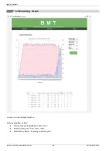
Page 38: ...MT series DOC 60425 05 21 36 8 8 Monitoring Graph 2 curves can be displayed together Channel selection vs time Torque Speed Angle degree and current Data sampling rate 5ms 10ms 15ms Data display option Fastening Loosening All ...

Page 39: ...l The tool is operated remotely for the followings Fastening loosening rotation Tool Start Tool lock unlock The following main signal status and I O are monitored and displayed together with torque speed and current curves Ready Tool start stop Torque up Fastening OK Alarm F R I O ...

Page 40: ...1 38 8 10 System Parameter Backup Back up file creation Click Back up icon to create the parameter setting back up file The file format is csv Parameter Update Load file The parameter back up file is loaded to the BM tool WiFi module Firmware update ...

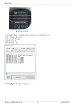
Page 41: ... 39 9 FIRMWARE UPGRADE Only with USB cable connection using ParaMon AirT software 1 Run a ParaMonAirT PC program 2 Click Update 3 Set Com Port Caution If cable disconnect during upgrade End program BM battery remove Start firmware upgrade first step ...

Page 42: ...5 05 21 40 Mise à jour du mode 4 Click Update Mode If already Update mode then don t click update mode 5 Check firmware update mode 6 Check Com Port change 7 Select firmware file 8 Click Firmware update 9 End the program after upgrade complete ...

Page 43: ...l is capable of connecting to a host controller Handy Loader HMI PLC PC etc through WiFi allowing the user to use such functions as parameter change and data monitoring Please refer to dedicated instruction manual BM COM protocol MODBUS TCP Please refer to register list in appendice ...

Page 44: ...tools 11 2 Trouble shooting During manufacturing the proper functioning of the unit is checked multiple times However if the unit malfunctions troubleshoot it using the error list in net chapter Warming All troubleshooting tasks requiring the opening of the box must be performed by DOGA or a company authorised by DOGA If you cannot resolve a problem despite reading this manual please contact the D...

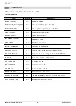
Page 45: ...r BAT_UNDER_VOLTAGE 111 Battery error signal OVER SPEED 112 Over Motor max speed DRIVER PARAMETER 113 Can t read driver parameter UNKNOWN DRIVER 114 Controller driver model setting different with driver NOT RECOGNIZE CTL 115 Program itself can not recognize the controller information NO SPEED 118 When motor rotation is not monitored WIFI COMM FAIL 120 Disconnect with AP USB COMM FAIL 122 USB commu...

Page 46: ...tting is out of the range AC TM mode MAX ANGLE 332 Target torque reached over the Max angle FASTENING STOP 333 Operation stops before complete cycle of torque up by releasin g lever trigger FIND ENGAGING TQ 334 The engaging torque is not detected in time or angle limit C_TORQUE LIMIT 335 Converted torque is out of torque limit FASTEN OVER TQ 336 Torque reached to the high limit of torque capacity ...

Page 47: ...e use of the tool Please contact your Technical Salespeople My client area on www doga fr Go to your client area on www doga fr click Your contacts then select your Technical Salespeople depending on the tool type 11 5 2 For any information regarding troubleshooting Please contact your After Sales contact My client area on www doga fr Go to your client area on www doga fr click Your contacts then ...

Page 48: ...unt and to invoice if applicable the costs of repairing and packaging 11 6 1 Download the after sales return form You can download the return form by following this link http service doga fr syst dogatech nsf liste 00184 Information You can use your own after sales service return form as long as it contains all the information necessary to take care of your equipment 11 6 2 Send your equipment The...

Page 49: ... fr click Your contacts then select your specific After sales contact depending on the device type Our services will organize the intervention 11 8 Waranty DOGA guarantee all his products against any defect in parts or fabrication for a period of 12 months To benefit from the parts and labor warranty the following conditions must be respected The tool must have been used in a professional use and ...

Page 50: ... of flammable liquids gases or dust Power tools create sparks which may ignite the dust or fumes Keep bystanders children and visitors away while operating a power tool Distractions can cause you to lose control 12 3 Electrical safety Grounded tools must be plugged into an outlet properly installed and grounded in accordance with all codes and ordinances Never remove the grounding prong or modify ...

Page 51: ...ding the work by hand or against your body is unstable and may lead to loss of control Do not force tool Use the correct tool for your application The correct tool will do the job better and safer at the rate for which it is designed Do not use tool if switch does not turn it on or off Any tool that cannot be controlled with the switch is dangerous and must be repaired Disconnect the plug from the...

Page 52: ...ducerized BMT series DOC 60425 05 21 50 12 7 Contra indications Do not cover Do not immerse Do not expose to splashing liquids Do not use near to a heat source Never lubricate aerosol oil on to the electrical part ...

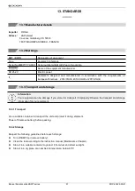
Page 53: ...irectives 2014 35 UE 2014 30 UE et 2011 65 UE 13 3 Transport and storage Information Your equipment can be damage if you store it or transport it improperly Observe the transport and storage information for your equipment 13 3 1 Transport Use a suitable container to transport the unit and protect it during shipment Power off remove battery before packing 13 3 2 Storage Respect the following guidel...

Page 54: ...e covering professsional Waste Electric and Electronic Equipment WEEE art R543 195 et seq DOGA is a member of ECOSYSTEM an eco organization approved by public authorities under the conditions defined by art R543 197 You can also benefit from collection and recycling system proposed by ECOSYSTEM for WEEE originating from the professional equipment marketed by DOGA Further information on www ecosyst...

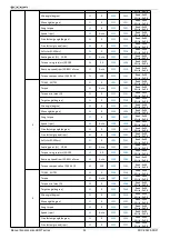
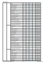
Page 55: ...rite 0x06 Min angle degree 5 0 1005 2005 Read 0x03 Write 0x06 Max angle degree 6 0 1006 2006 Read 0x03 Write 0x06 Snug torque 7 0 1007 2007 Read 0x03 Write 0x06 Speed rpm 8 Auto 1008 2008 Read 0x03 Write 0x06 Free fastenig angle degree 9 0 1009 2009 Read 0x03 Write 0x06 Free fastenig speed rpm 10 0 1010 2010 Read 0x03 Write 0x06 Soft start 1 300ms 11 0 1011 2011 Read 0x03 Write 0x06 Seating point ...

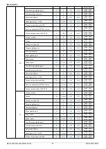
Page 56: ...5 Read 0x03 Write 0x06 Max angle degree 36 0 1036 2036 Read 0x03 Write 0x06 Snug torque 37 0 1037 2037 Read 0x03 Write 0x06 Speed rpm 38 Auto 1038 2038 Read 0x03 Write 0x06 Free fastenig angle degree 39 0 1039 2039 Read 0x03 Write 0x06 Free fastenig speed rpm 40 0 1040 2040 Read 0x03 Write 0x06 Soft start 1 300ms 41 0 1041 2041 Read 0x03 Write 0x06 Seating point 10 90 42 Auto 1042 2042 Read 0x03 W...

Page 57: ...Seating point 10 90 72 Auto 1072 2072 Read 0x03 Write 0x06 Torque rising rate ms 50 200 73 50 1073 2073 Read 0x03 Write 0x06 Ramp up speed rpm 20 80 of max 74 Auto 1074 2074 Read 0x03 Write 0x06 Torque compensation 90 110 75 100 1075 2075 Read 0x03 Write 0x06 6 TC AM_AC TM 76 0 1076 2076 Read 0x03 Write 0x06 Torque 77 Auto 1077 2077 Read 0x03 Write 0x06 Torque min max 78 0 1078 2078 Read 0x03 Writ...

Page 58: ... min max 108 0 1108 2108 Read 0x03 Write 0x06 Target angle degree 109 0 1109 2109 Read 0x03 Write 0x06 Min angle degree 110 0 1110 2110 Read 0x03 Write 0x06 Max angle degree 111 0 1111 2111 Read 0x03 Write 0x06 Snug torque 112 0 1112 2112 Read 0x03 Write 0x06 Speed rpm 113 Auto 1113 2113 Read 0x03 Write 0x06 Free fastenig angle degree 114 0 1114 2114 Read 0x03 Write 0x06 Free fastenig speed rpm 11...

Page 59: ...egree 144 0 1144 2144 Read 0x03 Write 0x06 Free fastenig speed rpm 145 0 1145 2145 Read 0x03 Write 0x06 Soft start 1 300ms 146 0 1146 2146 Read 0x03 Write 0x06 Seating point 10 90 147 Auto 1147 2147 Read 0x03 Write 0x06 Torque rising rate ms 50 200 148 50 1148 2148 Read 0x03 Write 0x06 Ramp up speed rpm 20 80 of max 149 Auto 1149 2149 Read 0x03 Write 0x06 Torque compensation 90 110 150 100 1150 21...

Page 60: ...2179 Read 0x03 Write 0x06 Torque compensation 90 110 180 100 1180 2180 Read 0x03 Write 0x06 13 TC AM_AC TM 181 0 1181 2181 Read 0x03 Write 0x06 Torque 182 Auto 1182 2182 Read 0x03 Write 0x06 Torque min max 183 0 1183 2183 Read 0x03 Write 0x06 Target angle degree 184 0 1184 2184 Read 0x03 Write 0x06 Min angle degree 185 0 1185 2185 Read 0x03 Write 0x06 Max angle degree 186 0 1186 2186 Read 0x03 Wri...

Page 61: ...x06 Snug torque 217 0 1217 2217 Read 0x03 Write 0x06 Speed rpm 218 Auto 1218 2218 Read 0x03 Write 0x06 Free fastenig angle degree 219 0 1219 2219 Read 0x03 Write 0x06 Free fastenig speed rpm 220 0 1220 2220 Read 0x03 Write 0x06 Soft start 1 300ms 221 0 1221 2221 Read 0x03 Write 0x06 Seating point 10 90 222 Auto 1222 2222 Read 0x03 Write 0x06 Torque rising rate ms 50 200 223 50 1223 2223 Read 0x03 ...

Page 62: ...x06 Sleep time 263 0 1263 2263 Read 0x03 Write 0x06 Auto lock 264 0 1264 2264 Read 0x03 Write 0x06 Select back up data type 265 6 1265 2265 Read 0x03 Write 0x06 Trigger start delay time 266 0 1266 2266 Read 0x03 Write 0x06 Network Setting Network enable 267 0 1267 2267 Read 0x03 Write 0x06 Static DHCP 268 0 1268 2268 Read 0x03 Write 0x06 Tool setting IP Address1 269 192 1269 2269 Read 0x03 Write 0...

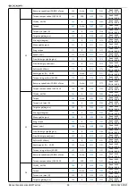
Page 63: ... 1336 2336 Read 0x03 Write 0x06 MS PG 17 337 0 1337 2337 Read 0x03 Write 0x06 MS PG 18 338 0 1338 2338 Read 0x03 Write 0x06 MS PG 19 339 0 1339 2339 Read 0x03 Write 0x06 MS PG 20 340 0 1340 2340 Read 0x03 Write 0x06 ERROR ERROR 1 341 0 1341 2341 Read 0x03 Write 0x06 ERROR 2 342 0 1342 2342 Read 0x03 Write 0x06 ERROR 3 343 0 1343 2343 Read 0x03 Write 0x06 ERROR 4 344 0 1344 2344 Read 0x03 Write 0x0...

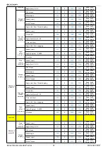
Page 64: ...e turn 0 20 516 0 1516 2516 Read 0x03 Write 0x06 Thread tapping Min torque 517 0 1517 2517 Read 0x03 Write 0x06 Max torque 518 0 1518 2518 Read 0x03 Write 0x06 Speed rpm 519 0 1519 2519 Read 0x03 Write 0x06 Finish Torque 520 0 1520 2520 Read 0x03 Write 0x06 Angle start from Thread tapping 521 0 1521 2521 Read 0x03 Write 0x06 Engaging torque detection Speed rpm 522 0 1522 2522 Read 0x03 Write 0x06 ...

Page 65: ...Read 0x04 Target torque x 100 3203 Read 0x04 Converted torque x 100 3204 Read 0x04 Target speed rpm 3205 Read 0x04 A1 degree 3206 Read 0x04 A2 degree 3207 Read 0x04 A3 degree 3208 Read 0x04 Screw count value 3209 Read 0x04 Error 3210 Read 0x04 Forward Loosening 3211 Read 0x04 Status Other 0 Fastening complete 1 Fastening NG E330 332 333 334 335 336 337 338 339 2 F L change 3 Preset change 4 Alarm ...

Page 66: ...ol Operation Alarm reset 4000 Write 0x06 Driver Lock 4001 Write 0x06 No use Factory only 4002 Write 0x06 Remote start 4003 Write 0x06 Preset change Not available on RUN 4004 Write 0x06 Forward Loosening 4005 Write 0x06 Barcode Control Operation Barcode list number 5000 Read 0x03 Write 0x06 Barcode preset number 5001 Read 0x03 Write 0x06 Barcode judge start position 5002 Read 0x03 Write 0x06 Barcod...

Page 67: ...Manual transducerized BMT series DOC 60425 05 21 65 ...

Page 68: ...cerized BMT series DOC 60425 05 21 66 Download the ultimate version of this manual via this link here below or via QR code http service doga fr syst dogatech nsf liste 60425 DOGA DOC 60391 12 20 DOGA DOC 60425 05 21 ...

Reviews: