HELIX ONE Mk2 INSTALLATION & OPERATION GUIDE
15
DA-MAN-H1-001
www.dohmannaudio.com
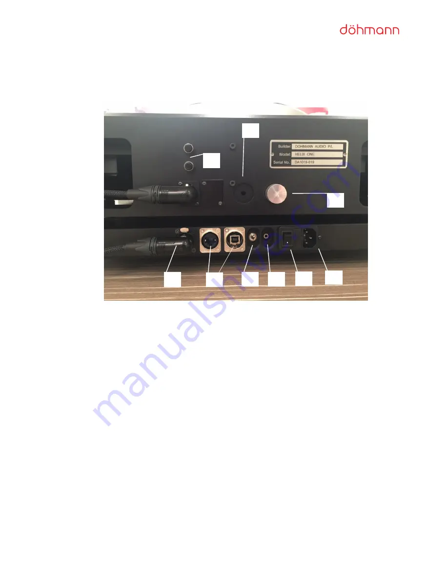
The Rear Panel of the Helix One and the PowerBase
The various sockets, switches and buttons that appear on the rear of the Helix One and the PowerBase are
explained below.
1:
The 5-Pin DIN cable
2:
Receptacles used to program the motor during servicing. Not used in normal operation. (Note: These
connections are blanked on most units)
3:
Toggle switch to operate LED lighting system
4:
Receptacle used for future vacuum upgrade. Not used in normal operation.
5:
Power Switch
6:
IEC mains socket
7:
Height Adjustment Knob
8:
Receptacle used for future vacuum upgrade. Not used in normal operation.
9:
Speed Adjust buttons
1
3
2
4
5
6
7
8
9


