background image

22

999775002 - 02/2020 

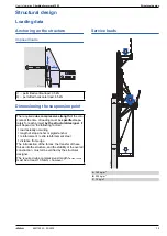
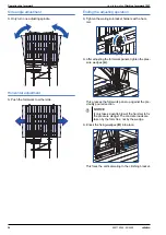
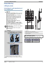
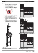
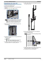
Anchoring on the structure

User Information 

Climbing formwork 150F

Preparing the suspension point

Dimensioning the suspension point

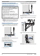
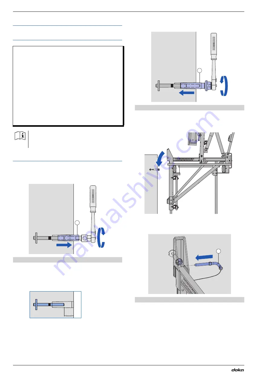
Engaging the climbing bracket

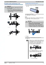
Unscrew the positioning cone, using a Reversible 

ratchet 1/2" and a Positioning-cone spanner 15.0 

DK.

Check of the positioning point

Check the code on the stop anchor.

Check the placement depth of the stop anchor.

a ... placement depth: 50 mm

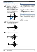
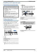
Screw in the climbing cone until this is fully engaged, 

and tighten it with a Reversible ratchet 1/2".

Suspend the climbing formwork from the climbing 

cones.

Insert the fastening pin with its handle in the horizon-

tal

The required 

cube compressive strength

 of the con-

crete at the time of loading must be 

specified

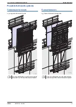
 sepa-

rately for each project 

by the structural designer

. It 

will depend on the following factors:


load actually occurring


length of stop anchor or pigtail anchor


reinforcement / extra reinforcement steel


distance from edge

The introduction of the forces, the transfer of these 

forces into the structure, and the stability of the overall 

construction, must all be verified by the structural 

designer.
The required cube compressive strength f

ck,cube,current


must be at least 10 N/mm

2

, however.

Follow the directions in the Calculation Guide 

entitled "Load-bearing capacity of anchorages 

in concrete" or ask your Doka technician!

A

Positioning cone 15.0 5cm

9775-226-02

A

9      -

775 269-21

a

B

Climbing cone 15.0 5cm

C

Fastening pin

9775-228-01

B

9775-229-01

9775-230-01

C

Summary of Contents for 150F

Page 1: ... Doka GmbH A 3300 Amstetten 999775002 02 2020 en GB The Formwork Experts Climbing formwork 150F User Information Instructions for assembly and use Method statement by Doka GmbH A 3300 Amstetten 9775 236 01 ...

Page 2: ...2 999775002 02 2020 User Information Climbing formwork 150F ...

Page 3: ...safe suspension point 27 Operating the formwork 27 Closing the formwork 28 Opening the formwork 29 Plumbing aligning the formwork 31 Repositioning 31 Lifting by crane 35 Operating the climbing formwork 35 Starting up 36 1st casting section 37 2nd casting section 40 3rd casting section 42 Assembly 42 Assembling the working platform 45 Mounting the Vertical waling and scissor action spindle 47 Mount...

Page 4: ...te This booklet serves as the basis for the site specific hazard assessment and for the instructions given to users on how to prepare and utilise the system It does not substitute for these however Remarks on this booklet This document can be used as general Instructions for Assembly and Use Method Statement or be incorporated into site specific Instructions for Assembly and Use Method Statement T...

Page 5: ...dden to weld Doka products in par ticular anchoring tying components suspension components connector components and castings etc or otherwise subject them to heating Welding causes serious change in the microstruc ture of the materials from which these components are made This leads to a dramatic drop in the failure load representing a very great risk to safety It is permissible to cut individual ...

Page 6: ...gress Eurocodes at Doka The permissible values stated in Doka documents e g Fperm 70 kN are not design values e g FRd 105 kN It is essential to avoid confusing permissible values with design values Doka documents will continue to state the permissi ble values Allowance has been made for the following partial fac tors γF 1 5 γM timber 1 3 γM steel 1 1 kmod 0 9 Consequently all the design values for...

Page 7: ... trained personnel assemble load bearing towers and formwork on site Just in time availability Formwork availability is a crucial factor in realising your project on time and on budget The worldwide logistics network puts the necessary formwork quanti ties on site at the agreed time Rental and reconditioning service The formwork material needed for any particular pro ject can be rented from Doka s...

Page 8: ...cm roll back for the formwork Easy to operate Fast set up and stripping of the formwork without crane Less crane time needed as the formwork repositions quickly as a complete unit Formwork can be adjusted in all directions both pre cisely and quickly Handy practical design high load bearing capacity 35 kN per Climbing bracket formwork heights of up to 6 0 m concrete loads transferred by way of for...

Page 9: ...mechanism with a scissor type function for aligning and repositioning the formwork elements or panels Permits up to 70 cm roll back Working platform Climbing bracket 150F D The Climbing bracket 150F is used for constructing the working platform and carries the retractable formwork element or panel Suspended platform Suspended platform 120 3 30m or 4 30m E 120 cm wide suspended platform for bolting...

Page 10: ...rk height 6000 b Distance between top of poured concrete and anchoring point 400 c Distance between suspension point and pressure strut 1250 f Width of bracket 1700 g Height of railings on bracket 1300 h Distance between bracket and suspended platform 2900 1 3900 2 i Width of suspended platform 1240 j Height of railings on suspended platform 1370 k Distance between formwork and concrete 670 l Heig...

Page 11: ... systems Timber beam formwork e g Large area formwork Top 50 Framed formwork e g framed formwork Framax Xlife For more information see the Timber beam formwork Top 50 User Information booklet 9775 239 01 For more information see the Framed form work Framax Xlife User Information booklet 9775 240 01 ...

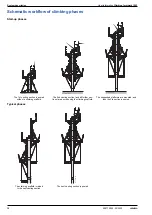
Page 12: ...ng section is poured without a climbing scaffold The 2nd casting section and all further sec tions are poured using the climbing scaffold The suspended platforms are mounted and then the 3rd section is poured The climbing scaffold is raised to the next casting section The next casting section is poured 9775 220 01 9775 241 01 9775 222 01 9775 243 01 9775 242 01 ...

Page 13: ...cified sepa rately for each project by the structural designer It will depend on the following factors load actually occurring length of stop anchor or pigtail anchor reinforcement extra reinforcement steel distance from edge The introduction of the forces the transfer of these forces into the structure and the stability of the overall construction must all be verified by the structural designer T...

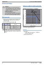
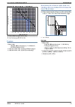
Page 14: ...ways take extra pre cautions to fix the formwork in place Suitable precautions set up the opposing formwork turn the screwjack mechanism until the form work meets the top of the previously cast sec tion and knock the fixing wedges into place Diagram Wind pressure kN m2 we cp net x q Ze Example A 1 00 Where cp net 1 3 Permissible wind speed 126 km h B 1 365 Where cp net 1 3 Permissible wind speed 1...

Page 15: ...the concrete When determining the influence width add the differ ence b 400 mm to the actual formwork height b min 400 mm Example Basic data Diagram B wind pressure 1 365 kN m2 formwork height 4 00 m distance between climbing cone and top of con crete b 0 65 m Formwork height for determining the influence width 4 00 m 0 65 m 0 40 m 4 25 m Influence width 2 25 m Formwork height m Influence width m ...

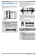
Page 16: ...ng cone 15 0 5cm A Stop anchor 15 0 expendable anchoring component B Depth mark C Positioning cone 15 0 5cm D Sealing sleeve 15 0 5cm expendable anchoring component E Climbing cone 15 0 5cm A Positioning cone 15 0 5cm B Sealing sleeve 15 0 5cm orange NOTICE Positioning cones 15 0 5cm are supplied together with Sealing sleeves 15 0 5cm Fit new sealing sleeves every time the cones are re used B D C ...

Page 17: ...he stop anchor type before and after the concrete has been poured A Stop anchor 15 0 a size of stop anchor plate 55 mm 16 b tie rod length 16 0 cm B Stop anchor 15 0 a size of stop anchor plate 90 mm 11 b tie rod length 11 5 cm A B 9710 82 3 01 e b c d 9775 269 03 a e b c d 9775 269 04 a WARNING The short Stop anchor 15 0 B11 has a much lower load bearing capacity than the Stop anchor 15 0 A16 The...

Page 18: ...ere is a risk of formwork falling off Unscrewing the anchor on one side may cause the anchor on the opposite side to shear off Do not under any circumstances connect cones with a tie rod a b c 9775 269 01 9775 269 01 A Positioning cone 15 0 5cm B Sealing sleeve 15 0 5cm expendable anchoring component C Stop anchor double ended 15 0 expendable anchoring compo nent D Super plate 15 0 E Tie rod 15 0m...

Page 19: ...269 11 A Positioning cone 15 0 5cm B Sealing sleeve 15 0 5cm orange WARNING Always screw the stop anchor into the posi tioning cone until it fully engages Not screwing the stop anchor fully into the cone may lead to reduced load bearing capacity and failure of the suspension point resulting in possible injury and or damage C Stop anchor 15 0 expendable anchoring component D Depth mark Always screw...

Page 20: ...ly e g where there are Doka beams or formwork panel frame profiles directly behind the positioning point Installation Nail a cantilever positioning cone to the form ply using a Fixing plate 15 0 position as shown in pro ject plan A Stop anchor 15 0 B Positioning cone 15 0 5cm Sealing sleeve 15 0 5cm C Super plate 15 0 D Tie rod 15 0mm If the positioning point is located too close to a Doka beam a ...

Page 21: ...ping the formwork Unscrew the Tie rod 15 0 The sealing sleeve must be completely pushed onto the positioning cone Always screw in components until they are fully engaged When correctly fitted there will still be 10 mm of thread visible between the part and the depth mark on the stop anchor or pigtail anchor Tolerance for locating the positioning points and suspension points 10 mm in the horizontal...

Page 22: ...ired cube compressive strength of the con crete at the time of loading must be specified sepa rately for each project by the structural designer It will depend on the following factors load actually occurring length of stop anchor or pigtail anchor reinforcement extra reinforcement steel distance from edge The introduction of the forces the transfer of these forces into the structure and the stabi...

Page 23: ...int Grout level with the rest of the surface Sealing of the suspension points can be a requirement for reasons of rust prevention Fill the cavity of the suspension point with mortar and grout it smoothly Fibre concrete plugs Remove the sealing sleeve Glue the fibre concrete plug into the hole of the sus pension point The concrete plug is glued into place with standard concrete adhesive C Fastening...

Page 24: ...g point Suspension point a length of plastic tube 3 4 cm b 15 16 cm Risk of confusion NEVER use Stop anchors 15 0 for this appli cation A Positioning cone 15 0 0 5cm Sealing sleeve 15 0 5cm B Tie rod 15 0mm C Universal cone 22mm Plastic tube 22mm D Super plate 15 0 E Climbing cone 15 0 5cm F Wall anchor 15 0 15cm G Hexagon timber screw 10x50 dowel Ø12 581893000 3 9775 269 18 a C B B D D A E F G b ...

Page 25: ...cannot be unscrewed The required cube compressive strength of the con crete and ready mix mortar at the time of loading must be specified separately for each project by the struc tural designer It will depend on the following factors load actually occurring wall thickness reinforcement extra reinforcement steel distance from edge The introduction of the forces the transfer of these forces into the...

Page 26: ...26 999775002 02 2020 Anchoring on the structure User Information Climbing formwork 150F ...
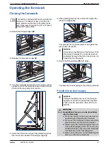
Page 27: ...e form work please see the User Information book lets Large area formwork Top 50 or Framed formwork Framax Xlife B 9775 258 03 A 9775 258 02 9775 201 01 NOTICE It only takes a gentle blow of the hammer to fix the pressure wedge The concrete loads are sustained by way of the form ties and are not transferred via the wedge NOTICE Improper handling and use of the formwork equipment can lead to hazard...

Page 28: ...edge A Roll back the formwork all the way by turning the screwjack mechanism of the scissor action spindle Tighten the pressure wedges A Knock the fixing wedges B into place This fixes the Vertical waling to the Climbing bracket B 9775 203 01 A 9775 205 01 9775 202 01 NOTICE The fixing wedge may only be released while the formwork is being retracted forward or back Final position fixing wedges kno...

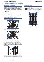
Page 29: ...n Detach the fixing wedges B Release the pressure wedge A Detach the formwork from the concrete Loosen the Waling to bracket holders B with a blow of the hammer The adjusting spindles C permit a vertical adjust ment range of approx 150 mm Also the adjusting spindles can be relocated in the hole grid of the Vertical waling D Vertical adjustment Turn both adjusting spindles E Timber wedges in the mu...

Page 30: ...olders with a ham mer After adjusting the formwork panels tighten the pres sure wedges A This presses the formwork panel up against the pre viously poured section Knock the fixing wedges B into place This fixes the vertical waling to the climbing bracket 9775 234 03 9775 234 01 NOTICE It only takes a gentle blow of the hammer to fix the pressure wedge The concrete loads are taken by the form ties ...

Page 31: ...iciently against oblique pull Tightening torque of couplers 50 Nm When using lifting beams ensure that these have sufficient load bearing capacity Length of chain at least the space between the hoisting points This automatically leads to the required spread angle β WARNING Any lifting brackets on the formwork pan els or Framax lifting hooks must not be used for lifting the unit as a whole Attach t...

Page 32: ...ponsible for positioning the access prohibition barriers correctly During the lifting repositioning cycle no site personnel are allowed to be on the units to be climbed or on adjacent units for reposi tioning The persons operating the climbing form work must use personal fall arrest systems to prevent falls during the lifting operation A Warning sign No entry 300x300mm 9775 244 01 a a A A Initial ...

Page 33: ...t 1 2 and Box spanner 41 Lift the entire unit by crane and hang it into place in the suspension point Secure the climbing formwork to the suspension points with fastening bolts Tighten the fixing nuts of the climbing cones using a Reversible ratchet 1 2 and Box spanner 41 If necessary mount a Wind bracing Before every lifting operation check to make sure that all bolted connections have been secur...

Page 34: ...34 999775002 02 2020 Repositioning User Information Climbing formwork 150F ...
Page 35: ...ions in question are Preparing the positioning points and suspension points see the section headed Anchoring on the structure Closing the formwork see the section headed Clos ing the formwork Stripping see the section headed Opening the form work In addition the following sections must also be observed Plumbing and aligning the formwork Repositioning by crane NOTICE There must be a flat firm base ...

Page 36: ...cessary mount positioning points for a Wind bracing Place the reinforcement Close the formwork and tie it Pour the 1st section a height of casting section b project specific Strike the formwork Clean the formwork Set the gang form down on a flat surface with the form ply facing downwards Prepare the formwork for the climbing operation A Positioning point B Positioning point for wind bracing 9775 2...

Page 37: ... MF 150F K 6 00m to the Climbing bracket 150 F with a d25 151 head bolt and a linch pin Fasten the tensioning unit of the Wind bracing MF 150F K 6 00m to the structure i e to the posi tioning point prepared with a climbing cone Tighten the Wind bracing MF 150F K 6 00m Formwork Attach the crane lifting tackle to the lifting brackets on the pre assembled formwork Crane lift the formwork to the worki...

Page 38: ...visions to safeguard improper lifting and repositioning of the unit as one piece e g nail on a board in such a way that the crane lift ing tackle cannot be hung into place in the lifting bracket Waling to bracket holder Waling to bracket holder 9 15cm H permitted horizontal load 11 kN H permitted horizontal load 22 kN A Waling to bracket holder 9 15cm B Height adjusting spindle C Timber wedges 980...

Page 39: ...rk 39 999775002 02 2020 Formwork set up and pouring Apply concrete release agent and set up one side of the formwork Mount the positioning points Place the reinforcement Close the formwork and tie it Pour the 2nd section Strike the formwork Clean the formwork 9775 241 01 ...

Page 40: ... lift out guard from the suspension points Loosen the fixing nuts of the climbing cones using a Reversible ratchet 1 2 and Box spanner 41 Lift the working platform to the pre assembled sus pended platforms Mount the suspended platform working from a mobile scaffold tower Bolt on the inside suspension tube with an M 16x120 hexagon bolt NOTICE When loosening the fixing nuts take care not to undo the...

Page 41: ... to the suspension points with fastening bolts Tighten the fixing nuts of the climbing cones using a Reversible ratchet 1 2 and Box spanner 41 If necessary mount a Wind bracing Formwork set up and pouring Apply concrete release agent and set up one side of the formwork Mount the positioning points Place the reinforcement Close the formwork and tie it Pour the 3rd section The fastening bolt must be...

Page 42: ...the platform beams Hole diameter 10 mm a centre to centre distance b 120 mm Bolt the Doka beams H20 to the climbing brackets Dimensions Length of wooden spacers approx 50 cm A Climbing bracket 150F Nail on stop blocks to ensure constant centre to centre distances 9775 215 01 a A 9775 213 02 Attachment scheme at front Attachment scheme at rear Bolts required for each connection included in scope of...

Page 43: ... Fasten deck boards to the Doka beams with Torx TG 6x90 A2 universal countersunk screws c 1700 mm x y diagonals Platform decking on the suspension point side d 20 mm Note The plank and board thicknesses stated comply with the EN 338 C24 timber Observe all national regulations applying to deck and guardrail boards D Scaffold tube 48 3mm E Screw on coupler 48mm 50 F Swivel coupler 48mm 9775 213 01 D...

Page 44: ...g bracket with a square bolt M10 Insert guard rail boards and use nails to secure them to the handrail post plates Bolting items needed for each handrail post upright 1 square bolt M10x60 1 washer A10 1 hexagon nut M10 Note The plank and board thicknesses given here comply with the C24 category of EN 338 Observe all national regulations applying to deck boards and guard rail boards Every deck boar...

Page 45: ...3 00m with a D25 120 head bolt and secure this with a Spring cotter 5mm Pin the spindle tube onto the Vertical waling 3 00m with the handle bolt Mounting the Vertical waling Remove the D25 120 head bolt from the bottom hole of the Vertical waling Attach the lifting chain to the lifting brackets of the Vertical waling and raise this pre assembled unit A Vertical waling 3 00m B Adjusting spindle Che...

Page 46: ...ixes the Vertical waling to the Climbing bracket Detach the lifting chain from the Vertical waling Fitting the bracing Move both Vertical walings 3 00m into the same position by turning the screwjack mechanism on the scissor action spindles Attach bracing scaffolding tubes Distance between screw on coupler and swivel cou pler max 160 mm Tightening torque of the couplers for the bracing tubes 50 Nm...

Page 47: ...eparing the formwork Set the formwork element down on a flat surface with the form ply facing downwards Mounting the pouring platform Attach Universal brackets and mount deck boards Also mount guard rail boards except where they would get in the way of the lifting chains when the gang form is lifted into the upright NOTICE It is not permitted to locate Multi purpose wal ings anywhere in the range ...

Page 48: ...n the width of the gang form Mounting the pouring platform Secure the Framax brackets and install the deck boards Also install Handrail posts 1 00m and guardrail boards except where they would get in the way of the lifting chains when the gang form is lifted into the upright Follow the directions in the Framed formwork Framax Xlife User Information booklet NOTICE As an additional precaution mount ...

Page 49: ... screws CAUTION There is a risk of the hexagon nuts working loose on the Brace stirrup 8 Fix the hexagon nuts on the Brace stirrup 8 with a Safety plate for brace stirrup 8 Always bend the anti twisting plate over the flat side of the hexagon nut Use each anti twisting plate once only A Platform profile B Brace stirrup 8 S Anti twisting plate for Brace stirrup 8 9775 232 01 B S 9775 253 01 A A Eve...

Page 50: ...r each tube Mounting the guard rail boards Attach a toeboard min 15x3 cm to the Handrail post upright with a square bolt M10 Insert guard rail boards and use nails to secure them to the handrail post plates Bolting items needed for each handrail post upright 1 square bolt M10x120 1 washer A10 1 hexagon nut M10 not included with product 9775 251 01 9775 262 01 9775 262 02 9775 250 01 ...

Page 51: ... clamps XP firmly to the decking supports clamping range 2 43 cm Working from below push a Toeboard holder XP 1 20m onto the Handrail post XP 1 20m Push the Handrail post XP 1 20m into the post hold ing fixture on the Railing clamps XP until the locking mechanism engages Fix guardrail boards to the Handrail post plates with nails diam 5 mm WARNING Exposed fall hazard location Danger to life from f...

Page 52: ...52 999775002 02 2020 Assembly User Information Climbing formwork 150F ...
Page 53: ...er Remove the two top guard rail boards from the pour ing platform Remove the waling to bracket holders and lift the formwork element or panel off the climbing unit Set down and dismantle the formwork element NOTICE A hard flat firm surface is needed Provide a sufficiently large dismantling space Read and observe the section headed Resetting by crane The fastening bolt must be pointing vertically ...

Page 54: ...s of the Vertical waling Dismount the Wind bracing Remove the fastening bolts lift out guard from the suspension points Gently raise the entire unit by crane and move it away from the building All other dismantling steps are carried out on the ground in the opposite order of steps from those in which the equipment was assembled 9775 267 01 9775 264 01 9775 211 01 ...

Page 55: ... in such a way that all national regulations are complied with Put up safety netting in the ladder and manhole zone as required by the applicable regulations A Manhole B 70 60cm B System ladder XS 4 40m C Ladder extension XS 2 30m D Ladder adapter XS E Ladder cage XS A D E 9775 255 01 B C WARNING The Ladders XS may only be used as part of the XS system and must NOT be used sep arately as lean to l...

Page 56: ...one another lift the safety latch on the ladder and fix the Ladder exten sion XS 2 30m onto the desired rung of the other lad der Ladder cage Fix the Ladder cage XS 1 00m E onto the next available rung The safety latches F prevent the cage being accidentally lifted out Add further Ladder cages XS 1 00m in each case fixing them onto the next available rung F Ladder bolt XS D Ladder adapter XS F 980...

Page 57: ... for small items To make the Doka skeleton transport box easier to load and unload one of its sidewalls can be opened Using Doka skeleton transport boxes 1 70x0 80m as storage units Max n of units on top of one another Using Doka skeleton transport boxes 1 70x0 80m as transport devices Lifting by crane Repositioning by forklift truck or pallet stacking truck The forks can be inserted under either ...

Page 58: ...1500 kg 3300 lbs Permitted imposed load 7850 kg 17300 lbs A Slide bolt for fixing the partition Multi trip transport box partition in the longitudinal direction in the transverse direction 1 20m max 3 partitions 0 80m max 3 partitions 9206 204 01 A 9206 204 02 9206 204 03 Max carrying capacity 750 kg 1650 lbs Permitted imposed load 7200 kg 15870 lbs Outdoors on the site Indoors Floor gradients up ...

Page 59: ...p boxes or pallets must have the heaviest boxes at the bottom and the lightest at the top How to use with Bolt on castor set B Always apply the fixing brake when the container is parked When Doka stacking pallets are stacked the bottom pallet must NOT be one with a bolt on caster set mounted to it NOTICE Multi trip packaging items may only be lifted one at a time Use a suitable crane suspension ta...

Page 60: ...a accessory box Doka stacking pallets Max carrying capacity 1000 kg 2200 lbs Permitted imposed load 5530 kg 12191 lbs Outdoors on the site Indoors Floor gradients up to 3 Floor gradients up to 1 3 6 It is not allowed to stack empty pallets on top of one another NOTICE Stacked multi trip boxes or pallets must have the heaviest boxes at the bottom and the lightest at the top How to use with Bolt on ...

Page 61: ...Handrail clamp T Fixed in embedded anchoring components or reinforcement hoops Guard rail boards or scaffold tubes can be used as the safety barrier a 1 00 m Handrail post 1 10m Fixed in a Screw sleeve 20 0 or Attachable sleeve 24mm Guard rail boards or scaffold tubes can be used as the safety barrier a 1 00 m Follow the directions in the Edge protection system XP User Information booklet Follow t...

Page 62: ... telescopic shaft beams for easy accommoda tion to any structure plan makes the system quick and easy to assemble facilitates attaching a follow up platform Easy to operate formwork can be set up and struck quickly with no need for a crane cuts back on crane time by enabling fast reposition ing of the entire unit platform plus shaft formwork Easy mounting system provides maximum safety with either...

Page 63: ...indabspannung MF 150F K 6 00m Wind bracing MF 6 00m 4 3 580677000 Windabspannung MF 6 00m Suspended platform 120 3 30m 44 0 580411000 Suspended platform 120 4 30m 52 6 580412000 Hängebühne 120 Top scaffold bracket L 12 6 587153500 Betonierkonsole L Top scaffold bracket L painted 12 0 587153000 Betonierkonsole L lackiert Universal bracket 90 30 4 580476000 Universal Konsole 90 Galvanised Width 173 ...

Page 64: ...000 Scaffold tube 48 3mm 4 00m 14 4 682021000 Scaffold tube 48 3mm 4 50m 16 2 682022000 Scaffold tube 48 3mm 5 00m 18 0 682023000 Scaffold tube 48 3mm 5 50m 19 8 682024000 Scaffold tube 48 3mm 6 00m 21 6 682025000 Scaffold tube 48 3mm m 3 6 682001000 Gerüstrohr 48 3mm Scaffold tube connection 0 27 584375000 Gerüstrohranschluss Screw on coupler 48mm 50 0 84 682002000 Screw on coupler 48mm 95 0 88 5...

Page 65: ...r 15 0 DK 0 30 580579000 Galvanised Length 8 cm Width across 30 mm Ladder system XS Manhole B 70 60cm 22 0 581530000 Bühnendurchstieg B 70 60cm Cover hinge SK 35cm 0 30 581533000 Deckelscharnier SK 35cm System ladder XS 4 40m 33 2 588640000 System Leiter XS 4 40m Ladder extension XS 2 30m 19 1 588641000 Leiternverlängerung XS 2 30m Ladder clamp SK 0 23 581239000 Leiternklemme SK Ladder bolt XS 0 8...

Page 66: ...ie rod 15 0mm non treated 1 00m 1 4 581874000 Tie rod 15 0mm non treated 1 25m 1 8 581886000 Tie rod 15 0mm non treated 1 50m 2 1 581876000 Tie rod 15 0mm non treated 1 75m 2 5 581887000 Tie rod 15 0mm non treated 2 00m 2 9 581875000 Tie rod 15 0mm non treated 2 50m 3 6 581877000 Tie rod 15 0mm non treated 3 00m 4 3 581878000 Tie rod 15 0mm non treated 3 50m 5 0 581888000 Tie rod 15 0mm non treate...

Page 67: ...ntainer Unterteilung Doka multi trip transport box 1 20x0 80x0 41m 42 5 583009000 Doka Mehrwegcontainer 1 20x0 80x0 41m Doka stacking pallet 1 55x0 85m 41 0 586151000 Doka Stapelpalette 1 55x0 85m Doka stacking pallet 1 20x0 80m 38 0 583016000 Doka Stapelpalette 1 20x0 80m Doka accessory box 106 4 583010000 Doka Kleinteilebox Bolt on castor set B 33 6 586168000 Anklemm Radsatz B Galvanised Length ...

Page 68: ...nd distributing formwork technology for use in all fields of the construction sector With more than 160 sales and logistics facilities in over 70 countries the Doka Group has a highly efficient dis tribution network which ensures that equipment and technical support are provided swiftly and profession ally An enterprise forming part of the Umdasch Group the Doka Group employs a worldwide workforce...

Reviews: