14
999803902 - 06/2014
Structural design
User Information
Dokaflex
30
tec
Structural design
Simple structural design
The spacings of the beams and floor props can be opti-
mised using the technical slide-rule.
Spacing and positions of the
component parts
Equipment usage can be fully optimised (see the sec-
tion headed "Optimising the structural design with
regard to equipment quantities").
An even more methodical and faster way of erecting
the formwork is to site-specifically base the spacings on
the 0.5
m grid shown by the spacing marks on the
beams.
You can tell at a glance whether the formwork has been
erected correctly, and without having to measure up.
For examples of site-specific grids, see the "Practical
examples".
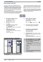
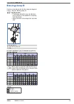
x ... 0.5 m
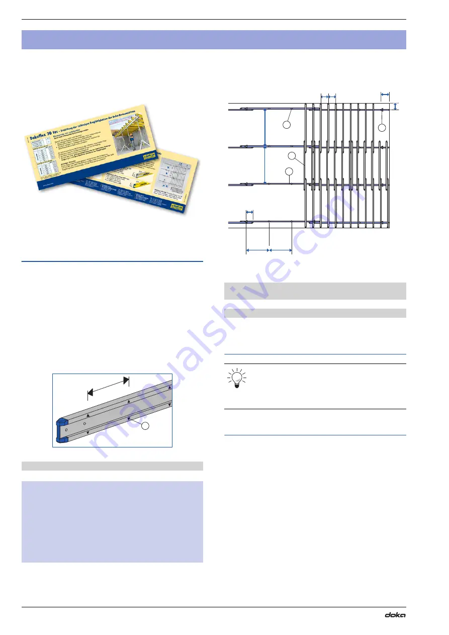
a ... spacing of props
b ... spacing of primary beams
c ... spacing of secondary beams, and distance from edge
Primary and secondary beams
Format of the formwork sheets
The ProFrame panels, in formats of
200x50cm
and
250x50cm
(21 or 27mm), have just the right dimen-
sions to fit exactly into the increment-grid of the Doka-
flex system.
Structural design
A
Mark
1 mark = 0.5
m
2 marks = 1.0
m
2
1
/
2
marks = 1.25
m
3 marks = 1.5
m
3
1
/
2
marks = 1.75
m
4 marks = 2.0
m
x
9768-202-01
A
A
"Main prop" (floor prop + Lowering head H20 + removable fold-
ing tripod)
B
"Intermediate prop" (floor prop + Supporting head H20
DF)
C
Doka beam H20 top (secondary beam)
D
Doka beam I
tec
20 (primary beam)
The primary beams should be orientated at
right angles to the direction of an uneven
length/width of room (5
m,
7 m,
9 m,
etc.).
This
makes more efficient use of the potential of the
system.
a a
b
b
c c
c
c
c
98039-202-01
A
B
C
D


