background image

User Information 

Dokaflex

 30

 tec

Introduction

5

999803902 - 06/2014

Rules applying during all phases of 
the assignment


The customer must ensure that this product is 

erected and dismantled, reset and generally used for 

its intended purpose in accordance with the applica-

ble laws, Standards and rules, under the direction 

and supervision of suitably skilled persons. These 

persons' mental and physical capacity must not in 

any way be impaired by alcohol, medicines or drugs.


Doka products are technical working appliances 

which are intended for industrial/commercial use 

only, always in accordance with the respective Doka 

User Information booklets or other technical docu-

mentation authored by Doka. 


The stability of all components and units must be 

ensured during all phases of the construction work!


The functional/technical instructions, safety warn-

ings and loading data must all be strictly observed 

and complied with. Failure to do so can cause acci-

dents and severe (even life-threatening) damage to 

health, as well as very great material damage.


Fire-sources are not permitted anywhere near the 

formwork. Heating appliances are only allowed if 

properly and expertly used, and set up a safe dis-

tance away from the formwork.


The work must take account of the weather condi-

tions (e.g. risk of slippage). In extreme weather, 

steps must be taken in good time to safeguard the 

equipment, and the immediate vicinity of the equip-

ment, and to protect employees.


All connections must be checked regularly to ensure 

that they still fit properly and are functioning cor-

rectly. 

It is very important to check all screw-type connec-

tions and wedge-clamped joins whenever the con-

struction operations require (particularly after excep-

tional events such as storms), and to tighten them if 

necessary.


It is strictly forbidden to weld Doka products – in par-

ticular anchoring/tying components, suspension 

components, connector components and castings 

etc. – or otherwise subject them to heating. 

Welding causes serious change in the microstruc-

ture of the materials from which these components 

are made. This leads to a dramatic drop in the failure 

load, representing a very great risk to safety.
The only articles which are allowed to be welded are 

those for which the Doka literature expressly points 

out that welding is permitted.

Assembly


The equipment/system must be inspected by the 

customer before use, to ensure that it is in suitable 

condition. Steps must be taken to rule out the use of 

any components that are damaged, deformed, or 

weakened due to wear, corrosion or rot.


Combining our formwork systems with those of other 

manufacturers could be dangerous, risking damage 

to both health and property. If you intend to combine 

different systems, please contact Doka for advice 

first.


The equipment/system must be assembled and 

erected in accordance with the applicable laws, 

Standards and rules by suitably skilled personnel of 

the customer's, having regard to any and all required 

safety inspections.


It is not permitted to modify Doka products; any such 

modifications constitute a safety risk.

Closing the formwork


Doka products and systems must be set up so that 

all loads acting upon them are safely transferred!

Pouring


Do not exceed the permitted fresh-concrete pres-

sures. Over-high pouring rates overload the form-

work, cause greater deflection and risk breakage.

Stripping out the formwork


Do not strip out the formwork until the concrete has 

reached sufficient strength and the person in charge 

has given the order for the formwork to be stripped 

out!


When stripping out the formwork, never use the 

crane to break concrete cohesion. Use suitable tools 

such as timber wedges, special pry-bars or system 

features such as Framax stripping corners.


When stripping out the formwork, do not endanger 

the stability of any part of the structure, or of any 

scaffolding, platforms or formwork that is still in 

place!

Summary of Contents for Dokaflex 30 tec Series

Page 1: ... 999803902 06 2014 en GB The Formwork Experts User Information Instructions for assembly and use Method statement Dokaflex 30 tec 98039 200 01 ...

Page 2: ...2 999803902 06 2014 Introduction User Information Dokaflex 30 tec Introduc tion by Doka Industrie GmbH A 3300 Amstetten ...

Page 3: ...ructural design with regard to equipment quantities 18 Instructions for assembly and use 24 Adaptability 25 Secondary beam stabilisers 26 Floor formwork around edges 28 Tie back solutions 29 Bracing clamp B 30 Slab stop ends 32 Fall arrest systems on the structure 33 Beam forming support 34 Drop beam not integrated into the floor slab stop end formwork 35 Drop beam integrated into the floor slab 3...

Page 4: ...g a hazard assessment at every job site This document serves as the basis for the site spe cific hazard assessment and for the instructions given to users on how to prepare and utilise the sys tem It does not substitute for these however Remarks on this document This manual can also be used as a generic method statement or incorporated with a site specific method statement Many of the illustration...

Page 5: ...r anchoring tying components suspension components connector components and castings etc or otherwise subject them to heating Welding causes serious change in the microstruc ture of the materials from which these components are made This leads to a dramatic drop in the failure load representing a very great risk to safety The only articles which are allowed to be welded are those for which the Dok...

Page 6: ...ts Repairs may only be carried out by the manufacturer or authorised facilities Miscellaneous We reserve the right to make alterations in the interests of technical progress Symbols used The following symbols are used in this booklet Important note Failure to observe this may lead to malfunc tion or damage CAUTION WARNING DANGER Failure to observe this may lead to material damage and to injury to ...

Page 7: ...d Design value of an action Steel Rd Rk Timber Rd kmod Rk Fd F Fk M M F force Fk Characteristic value of an action actual load service load k characteristic e g dead weight live load concrete pressure wind Rk Characteristic value of the resistance e g moment resistance to yield stress F Partial factor for actions in terms of load F force e g for dead weight live load concrete pres sure wind Values...

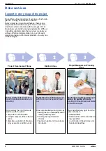
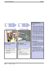
Page 8: ...ject Management Planning Stage Taking well founded decisions thanks to professional advice and consulting Optimising the preliminary work with Doka as an experienced part ner Controlled regular forming oper ations for greater efficiency resulting from realistically calculated formwork concepts Find precisely the right formwork solutions with the aid of help with the bid invitation in depth analysi...

Page 9: ...completely transparent there is no need for improvisation dur ing the project and no unpleas ant surprises at the end of it Reduced close out costs Our professional advice on the selection quality and correct use of the equipment helps you avoid damage and minimise wear and tear Concrete Construction Stage Project Close out Stage Optimum resource utilisation with assistance from the Doka Formwork ...

Page 10: ...10 999803902 06 2014 Introduction User Information Dokaflex 30 tec ...

Page 11: ...ment Benefit right across the board Based on existing system components Reduced storage and transport volumes Multi functional system components that can also be used in other Doka formwork solutions Simply by telescoping the I tec 20 primary beams and the H20 top secondary beams Dokaflex 30 tec adapts to any desired layout The formwork is planned with a technical slide rule ensuring that it is op...

Page 12: ...long service life pre defined positioning points as reference marks for setting up and checking the formwork C Doka beam I tec 20 is used as the primary beam Characteristic features dark grey beam end reinforcement grey web and grey plastic sheets on the flange integrated shock absorber on the beam end piece for reduced damage and long service life pre defined positioning points as reference marks...

Page 13: ...the prop eas ier to release even when it is under high load elbowed fastening clamps reducing the risk of injury and making the props easier to operate Note The floor props can be lengthened with the Floor prop extension 0 50m allow for the reduced load bearing capacity G Removable folding tripod for holding floor props upright swing out legs allow flexible placement in con stricted situations suc...

Page 14: ... the Practical examples x 0 5 m a spacing of props b spacing of primary beams c spacing of secondary beams and distance from edge Primary and secondary beams Format of the formwork sheets The ProFrame panels in formats of 200x50cm and 250x50cm 21 or 27mm have just the right dimen sions to fit exactly into the increment grid of the Doka flex system Structural design A Mark 1 mark 0 5 m 2 marks 1 0 ...

Page 15: ...chosen 2 50 m 3 For a permitted prop load of 25 kN max spacing of props 1 09 m Value chosen 1 00 m 4 For a permitted prop load of 35 kN max spacing of props 1 53 m Value chosen 1 50 m Practical examples Spacing of props a 1 00 m1 1 System grid 1 2 5 markings on beams for beam lengths of 4 90m and 3 90m Spacing of props a 1 25 m Spacing of props a 1 50 m2 2 System grid 1 3 5 markings on beams for b...

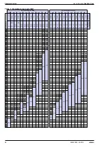
Page 16: ...6 36 5 5 5 20 6 22 7 36 7 31 8 33 3 5 4 21 6 23 9 33 6 35 3 5 3 22 5 25 2 35 5 37 2 5 2 23 6 26 5 37 3 39 2 5 1 24 7 27 9 39 2 41 0 5 0 25 8 29 4 41 2 41 2 4 9 27 2 31 0 4 8 28 7 32 5 4 7 30 1 34 2 4 6 31 6 35 9 4 5 33 2 36 7 32 7 34 5 4 4 34 9 34 8 36 8 4 3 36 7 36 8 39 2 4 2 39 2 41 2 4 1 41 2 4 0 21 5 24 8 31 5 34 2 3 9 23 0 26 8 33 8 36 8 3 8 24 4 28 7 36 1 39 3 3 7 26 0 30 8 38 7 41 2 3 6 27 ...

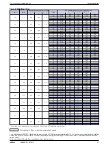
Page 17: ...0 2 26 2 05 1 71 1 67 1 39 35 2 26 2 05 1 92 1 90 1 62 40 2 26 2 05 1 92 1 90 1 79 24 7 7 3 24 2 82 2 61 25 2 17 1 63 1 33 1 30 1 08 30 2 20 1 95 1 60 1 56 1 30 35 2 20 2 00 1 87 1 82 1 52 40 2 20 2 00 1 87 1 85 1 68 26 8 2 3 15 2 75 2 55 25 2 04 1 53 1 25 1 22 1 02 30 2 14 1 83 1 50 1 47 1 22 35 2 14 1 95 1 75 1 71 1 43 40 2 14 1 95 1 82 1 81 1 58 28 8 7 3 08 2 68 2 49 25 1 92 1 44 1 18 1 15 0 96...

Page 18: ...tc we recommend fastening this tripod to an adjacent floor prop instead where there is room for the legs to be completely unfolded b spacing of primary beams x depending on the number of intermediate props x 2 3 or 4 times the prop spacing a given in Dimensioning Important note As well as the instructions given here you MUST follow the instructions in Reshoring props concrete technology and stripp...

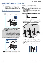
Page 19: ... The spacings of the props and pri mary beams are dimensioned for the higher load bearing capacity of this beam Planks can be attached to the floor props as diagonal braces using the Bracing clamp B 9720 003 98039 208 01 9776 201 01 WARNING It is not permitted to set down any loads on the floor slab formwork e g beams panels reinforcements until the intermediate props have been set up If it is pla...

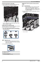
Page 20: ...l spring steel stirrup Put up the intermediate props Laying the ProFrame panels on the beams from below Lay the ProFrame panels at right angles to the sec ondary beams a spacing of props Important note Put up the intermediate props so that they force fit It is not allowed to make some props higher than others A Supporting head H20 DF B Doka beam I tec 20 C Hole in the supporting head for fixing wi...

Page 21: ...ems PFAS when setting up the form work from above a a a 98039 210 01 Where necessary e g edge zones secure the form ply with nails Recommended nail lengths sheet thickness 21 mm approx 50 mm sheet thickness 27 mm approx 60 mm Windproofing For increased stability in larger rooms the full erection sequence of primary beams secondary beams formwork sheets should be carried out progressively for suc c...

Page 22: ...nd scaffold DF collapsible wheelaround platform made of light alloy variable working heights of up to 3 50 m max platform height 1 50 m width of scaffold 0 75 m When work is being carried out near drop off edges i e at a distance of 2 m the Wheel around scaffold DF accessory set consisting of a toeboard and intermediate guardrail is needed For greater heights the Working scaffold Modul is ideal 97...

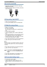
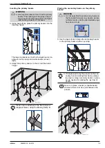
Page 23: ...ing pallet Removing the floor props 1 Hold the inner tube with one hand 2 Open the fastening clamp to unfix the inner tube Guide this by hand while lowering it into the outer tube Put the removable folding tripods and props in the stacking pallet Reshoring Before pouring the next floor slab i e above the one that has just been stripped put up reshoring props 9720 007 9720 008 9720 009 When lifting...

Page 24: ...made by overlapping the Doka beams and inserting strips of formwork sheeting Grid and flexibility in one system Dokaflex also adapts to difficult layouts Adaptation along edge Adaptation around columns A ProFrame panel B Fitting boards in the closure zone The grain of the face layer A must run at right angles to the supports B 9720 336 01 9768 209 01 A B 9776 200 01 A B 9792 210 01 B A 9720 211 01...

Page 25: ...he formwork erection cycle approx 20 Secondary beam stabilisers 1 approx 10 Secondary beam stabilisers 2 Note In certain special situations e g when forming inclined floor slabs Secondary beam stabilisers can also be used for transferring horizontal loads For more information please contact your Doka techni cian How to mount Hang the Secondary beam stabilisers into place with an Alu beam fork H20 ...

Page 26: ...Dokamatic table platform D Lashing strap 5 00m E Doka express anchor 16x125mm and Doka coil 16mm A Load bearing tower B Dokaflex C Staxo 40 bracket 90cm D Edge protection system XP E Plumbing strut 340 for pre cast members F Doka express anchor 16x125mm and Doka coil 16mm 9720 338 01 A C D B E 98039 215 01 A B D D E C F A Dokamatic table B Dokaflex C Handrail post T 1 80m with Toeboard holder T 1 ...

Page 27: ...nother The back stay can be fastened to either the second ary or primary beam WARNING For work at dangerous heights the second ary beam elements with the working plat forms must be preassembled on the ground Where working platforms are erected on cantilevering floor slab formwork the form work must be secured against accidental lift out Secondary beams with stop end formwork must be secured agains...

Page 28: ... placed through a beam hole Lifting bracket Pre mounted to primary beam H Horizontal load V Vertical load A Back stay force WARNING Never attach the tie back directly to a head unit or floor prop Max tie back load 5 kN A Lashing strap 5 00m Tr784 200 01 H A V Tr784 208 01 Tr784 200 01 A Max tie back load 5 kN A Lashing strap 5 00m B Diam 20 mm tie rod or reinforcement rod Max tie back load 5 kN A ...

Page 29: ...r in the wedge from top to bot tom A Bracing clamp B B Doka floor prop Eurex 30 C Plank Eurex 20 top Plank 2 4 x 15 3 x 15 4 x 15 5 x 10 5 x 12 5 x 15 IT OT IT OT IT OT IT OT IT OT IT OT 150 250 300 350 400 550 When used in conjunction with the Floor prop Eurex 20 top 700 please refer to the User Infor mation booklet for this system Eurex 30 top Plank 2 4 x 15 3 x 15 4 x 15 5 x 10 5 x 12 5 x 15 IT...

Page 30: ... striking formwork Take out the nails on the stop end side Put the claw of a hammer under the corner put a piece of wood under it to protect the formwork sheeting Lever up the end shutter support 9776 202 01 d B A B C Tr652 203 02 A Universal end shutter support 30cm C Doka formwork sheet 3 SO D Spax screws 4x40 fully threaded E Doka beam H20 Max influence width a for slab thickness of cm How fast...

Page 31: ...mounted and dismounted from either above or below when the End shutter shoe is used Low unit weight can be separated into 2 parts System dimensions a1 15 57 5 cm with End shutter shoe a2 18 57 5 cm using a Tie rod 15 0 and Bridge edge beam anchor 15 0 b formwork overlap min 2 cm as a rule 5 cm c stop end width 2 15 cm d slab thickness max 60 cm Practical example Note The edge railings must be moun...

Page 32: ...ponents or reinforcement hoops Guard rail boards or scaffold tubes can be used as the safety barrier a 1 00 m Handrail post 1 10m Fixed in a Screw sleeve 20 0 or Attachable sleeve 24mm Guard rail boards or scaffold tubes can be used as the safety barrier a 1 00 m Follow the directions in the Doka floor end shutter clamp User Information booklet Follow the directions in the Edge protection system X...

Page 33: ...of the Beam forming sup port gives the sidewall formwork a high degree of 90 angle accuracy Clamp the Beam forming support firmly into position The diagonal bracing of the Beam forming support ensures that the joint between the form ply sheets is automatically pressed together tightly when the Beam forming support is clamped This results in a clean concrete surface Formwork beams horizontal up to ...

Page 34: ...and 90 cm in height b max 100 cm l max 150 cm Sidewall formwork Doka formwork beams H20 in the upright h Drop beam height b Drop beam width l Spacing of primary beams Spacing of secondary beams Position of Beam forming support 50 0 cm On every 3rd secondary beam Spacing of secondary beams Position of Beam forming support 50 0 cm On every 2nd secondary beam 9720 249 01 h b l 9720 250 01 h b l h Spa...

Page 35: ...ax 100 cm l max 150 cm Sidewall formwork 2 Doka beams H20 top Drop beams of between 60 and 70 cm in height b max 100 cm l max 150 cm Sidewall formwork 2 Doka beams H20 top Height of squared timber h 60 cm Slab thickness d Spacing of secondary beams Position of Beam forming support 20 cm 30 cm 62 5 cm 41 7 cm On every 2nd secondary beam On every 3rd secondary beam Slab thickness d Spacing of second...

Page 36: ...x 100 cm l max 150 cm Sidewall formwork Doka beam H20 top Squared timber 5 8 cm for drop beams of between 51 and 60 cm in height Squared timber 10 8 cm for drop beams of between 60 and 70 cm in height h Drop beam height b Drop beam width l Spacing of primary beams Slab thickness d Spacing of secondary beams Position of Beam forming support 20 cm 30 cm 62 5 cm 41 7 cm On every 2nd secondary beam On...

Page 37: ...sembled and save on both labour and crane time With the DoKart the tables can easily be wheeled across to their next location by just one man working on his own The system is optimised to give the very shortest forming times on large areas and copes well even with varying structural design and geometrical requirements For more information see the Dokamatic table Dokaflex table Doka load bearing to...

Page 38: ...lution to your form work task This makes for greater operational reliability and cuts costs You can get to work right away with the piece lists plans views sections and perspective drawings that the program gives you Operational reliability is also enhanced by the high level of detail of the plans Formwork drawings really can be as clear and detailed as this Both for the layout and for spatial rep...

Page 39: ...lti trip packaging on your site Multi trip packaging such as containers stacking pal lets and skeleton transport boxes keep everything in place on the site minimise time wasted searching for parts and streamline the storage and transport of sys tem components small items and accessories Max load 700 kg Permitted imposed load 3150 kg Multi trip packaging items that each contain very different loads...

Page 40: ...The forks can be inserted under either the broadside or the narrowside of the containers Max load 1500 kg Permitted imposed load 7900 kg Multi trip packaging items that each contain very different loads must be stacked with the heaviest ones at the bottom and the lightest ones at the top Rating plate must be in place and clearly leg ible A Slide bolt for fixing the partition Tr755 200 02 A Multi t...

Page 41: ... must be in place and clearly leg ible Outdoors on the site Indoors Floor gradient up to 3 Floor gradient up to 1 2 6 It is not allowed to stack empty pallets on top of one another How to use with bolt on castor set Always apply the fixing brake when the con tainer is parked When Doka stacking pallets are stacked the bottom pallet must NOT be one with a bolt on caster set mounted to it Multi trip ...

Page 42: ...ti trip packaging items Doka accessory box Doka stacking pallets Follow the directions in the Bolt on castor set B Operating Instructions Max load 1000 kg Permitted imposed load 5530 kg Multi trip packaging items that each contain very different loads must be stacked with the heaviest ones at the bottom and the lightest ones at the top Rating plate must be in place and clearly leg ible Outdoors on...

Page 43: ...things in one base rest profile lashing strap and edge protection ProFrame panels are delivered ex works strapped together with Stacking straps 50 Two Stacking straps 50 are needed per stack of panels It can also be used in conjunction with the wheel around Doka stacking pallet for handling stacks of panels with no need for a crane ProFrame panels 21mm 50 units ProFrame panels 27mm 40 units 98039 ...

Page 44: ...ound in DIN 1045 3 2008 Table 2 The length of time until 50 percent of the final 28 day strength is reached can be read off from this Table as a function of the temperature and the type of concrete The values are only valid if the concrete is given cor rect appropriate curing throughout the entire period For a concrete with medium strength development the following inferred diagram may thus be use...

Page 45: ...reinforced concrete constructions Other cracking phenomena can be countered effec tively by appropriate curing methods Curing of new concrete New site placed concrete is exposed to influences which may cause cracking and slow down its strength development premature drying over rapid cooling in the first few days excessively low temperatures or frost mechanical damage to the surface of the concrete...

Page 46: ...a floor prop Eurex 20 400 22 2 586089000 Length 227 400 cm Doka floor prop Eurex 20 550 34 6 586090000 Length 297 550 cm Doka Deckenstütze Eurex 20 Doka floor prop Eurex 30 top 250 12 8 586092400 Length 148 250 cm Doka floor prop Eurex 30 top 300 16 4 586093400 Length 173 300 cm Doka floor prop Eurex 30 top 350 20 7 586094400 Length 198 350 cm Doka floor prop Eurex 30 top 400 24 6 586095400 Length...

Page 47: ...rt 20 6 9 586148000 Balkenzwinge 20 Extension for beam forming support 60cm 4 4 586149000 Balkenaufsatz 60cm Doka floor end shutter clamp 12 5 586239000 Doka Deckenabschalklemme End shutter shoe 1 6 586257000 Abschalschuh End shutter tie rod 15 0 15 40cm 0 91 586258000 Abschalanker 15 0 15 40cm Platform stairway 0 97m 23 5 586555000 Podesttreppe 0 97m Galvanised Length 25 cm Width 20 cm Height 38 ...

Page 48: ...beam H20 top N 2 90m 15 0 189014000 Doka beam H20 top N 3 30m 17 0 189015000 Doka Träger H20 top N Doka beam H20 top P 2 65m 14 3 189703000 Doka beam H20 top P 2 90m 15 6 189704000 Doka beam H20 top P 3 30m 17 7 189705000 Doka Träger H20 top P ProFrame panel 21mm 200 50cm 11 0 186118000 ProFrame panel 21mm 200 50cm BS 11 0 186118100 ProFrame panel 21mm 250 50cm 13 8 186117000 ProFrame panel 21mm 2...

Page 49: ... Gerüstrohr 48 3mm Screw on coupler 48mm 50 0 84 682002000 Anschraubkupplung 48mm 50 Multi trip packaging Doka multi trip transport box 1 20x0 80m 75 0 583011000 Doka Mehrwegcontainer 1 20x0 80m Multi trip transport box partition 0 80m 3 7 583018000 Multi trip transport box partition 1 20m 5 5 583017000 Mehrwegcontainer Unterteilung Doka accessory box 106 4 583010000 Doka Kleinteilebox Bolt on cas...

Page 50: ...2014 Component overview User Information Dokaflex 30 tec Doka stacking pallet 1 20x0 80m 39 5 583016000 Doka Stapelpalette 1 20x0 80m Stacking strap 50 3 1 586156000 Stapelgurt 50 Galvanised Height 77 cm Powder coated blue Packaging unit 2 pcs ...

Page 51: ...User Information Dokaflex 30 tec Component overview 51 999803902 06 2014 ...

Page 52: ...ng and distributing formwork technology for use in all fields of the construction sector With more than 160 sales and logistics facilities in over 70 countries the Doka Group has a highly efficient dis tribution network which ensures that equipment and technical support are provided swiftly and profession ally An enterprise forming part of the Umdasch Group the Doka Group employs a worldwide workf...

Reviews: