background image

User Information 

Framed formwork Framax Xlife plus

Wall formwork

61

999811202 - 04/2019

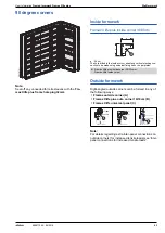
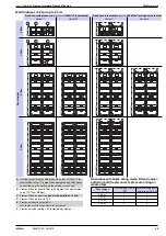
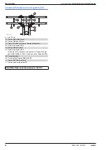
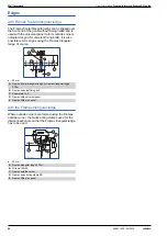
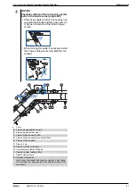
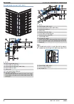
Wall thickness up to 40


cm

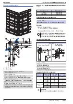
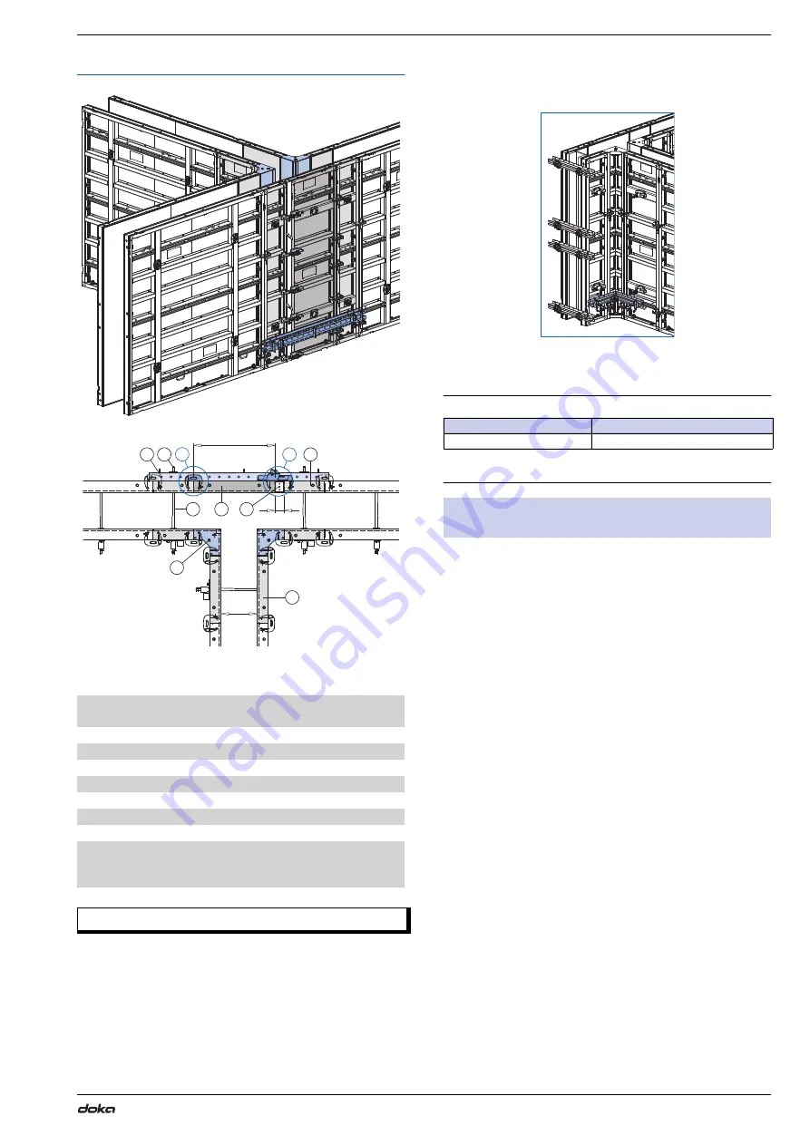
a ... Wall thickness (max. 40


cm) 

b ... Panel width  
c ... Closure width

Note:
If the wall sections are short

 it is advisable to brace 

the inside corner with a 

universal corner waling

.

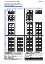
Width of the Framax Xlife plus panel in the straight 
wall

Closure width in the straight wall

Example:

 ▪

Wall thickness = 40


cm  

=> Panel width (b) = 

90

  cm (0.90m)


Closure width = 60


cm - 90


cm - 40


cm = 

10

  cm

A

Framax Xlife plus inside corner 30/30cm or  
Framax Xlife inside corner

B

Framax Xlife plus panel 

0.90m

C

Framax Xlife plus panel 

(max. width of 0.30m)

D

Framax Xlife plus panel 

(max. width of 0.90m)

E

Closure 

0 - 15 cm

 (Framax alu closure / Framax fitting timber)

G

Tie rod system Framax Xlife plus 20.0

H

Multi-purpose waling WS10


Top50

I

Framax wedge clamp

J

Inter-panel connection (see the section headed 'T-junction: 
Inter-panel connections on Framax Xlife plus panels in the 
straight wall')

Permitted fresh-concrete pressure: 

60kN/m²

9        -      -018112

344

a

b

c

9        -      -0

8112 344 2

A

B

E

D

G

J

J

C

H

I

Wall thickness (

a

)

Panel width (

b

)

>30 - 40


cm

0.90m (90


cm)

Closure width 

c

 =  

60

  cm + wall thickness 

a

 [cm] - panel width 

b

 [cm]

98112 346

-      -01

Summary of Contents for Framed formwork Framax Xlife plus

Page 1: ...bH A 3300 Amstetten 999811202 04 2019 en GB The Formwork Experts Framed formwork Framax Xlife plus User Information Instructions for assembly and use Method statement by Doka GmbH A 3300 Amstetten 9 20 0 8112 7 1 ...

Page 2: ...2 999811202 04 2019 User Information Framed formwork Framax Xlife plus ...

Page 3: ...nt using closures 53 90 degree corners 65 Acute obtuse angled corners 71 Shaft formwork 79 Inter panel connections for increased tensile loads 80 Stop end formwork 83 Wall junctions offsets and steps 85 Window and door openings 86 Plumbing accessories 89 Pouring platforms 96 Pouring platforms with single brackets 98 Opposing guard rail 101 Wall formwork at the edge of the structure 103 Ladder syst...

Page 4: ...ob site This booklet serves as the basis for the site specific hazard assessment and for the instructions given to users on how to prepare and utilise the system It does not substitute for these however Remarks on this booklet This document can be used as general Instructions for Assembly and Use Method Statement or be incorporated into site specific Instructions for Assembly and Use Method Statem...

Page 5: ... forbidden to weld Doka products in par ticular anchoring tying components suspension components connector components and castings etc or otherwise subject them to heating Welding causes serious change in the microstruc ture of the materials from which these components are made This leads to a dramatic drop in the failure load representing a very great risk to safety It is permissible to cut indiv...

Page 6: ...s as stated are averages for new material actual weights can differ depending on material toler ances Dirt accretions moisture saturation etc can also affect weight We reserve the right to make alterations in the interests of technical progress Symbols used The following symbols are used in this document DANGER This is a notifier drawing attention to an extremely dangerous situation in which non c...

Page 7: ...pouring processes optimise inventories and create more efficient formwork planning processes Custom formwork and on site assembly To complement its system formwork range Doka offers customised formwork units And specially trained personnel assemble load bearing towers and formwork on site Just in time availability Formwork availability is a crucial factor in realising your project on time and on b...

Page 8: ...tubes and cones wide spacing between form ties 1 35 m apart saves up to twelve per cent of the costs for form tie points and finishing work on form tie holes high numbers of repeat uses made possible by excellent manufacturing quality and extra durable Xlife sheets steel frames are hot dip galvanised both inside and out for long lifespan form ties are opened and closed using a ratchet for minimal ...

Page 9: ...of panels Page 26 D Tie rod system Page 40 E Length adjustment Page 52 F 90 degree corners Page 53 G Acute obtuse angled corners Page 65 H Stop end formwork Page 80 I Plumbing accessories Page 86 J Pouring platforms Page 89 K Opposing guard rail Page 98 L Ladder system Page 103 M Lifting by crane Page 108 9 01 8112 341 B D E F G H I A J M C L K Permitted fresh concrete pressure 80 kN m2 ...

Page 10: ...lifting hook see the section headed Lifting by crane and the Operat ing Instructions for the Framax lifting hook Raise the gang form by crane Spray the formwork sheet with release agent see the section headed Cleaning and care of your equip ment Fly the gang form to its new location Fix the panel struts firmly to the ground see the sec tion headed Plumbing accessories The gang form is now stable a...

Page 11: ...Continue lining up further gang forms in this way and link them together see Inter panel connec tions Pouring Observe the following guidelines The section headed Pressure of fresh concrete on vertical formwork DIN 18218 in the Calculation Guide Doka formwork engineering DIN 4235 Part 2 Compacting of concrete by vibrat ing Pour the concrete WARNING There is not yet an opposing guard rail on the for...

Page 12: ...t must not be parked upright but placed face down Clean residual concrete off the formwork sheet see the section headed Cleaning and care Where the gang form has panel struts and a pouring platform attached to it first attach this gang form to the crane and only then detach the floor anchorages of the panel struts NOTICE Comply with the stipulated stripping times 98112 226 01 98112 226 02 In order...

Page 13: ...m by crane Spray the formwork sheet with release agent see the section headed Cleaning and care of your equip ment Fly the gang form to its new location Fix the panel struts firmly to the ground see the sec tion headed Plumbing accessories The gang form is now stable and can be plumbed and aligned exactly with no need for the crane Detach the gang form from the crane Continue lining up further gan...

Page 14: ...ng guidelines The section headed Pressure of fresh concrete on vertical formwork DIN 18218 in the Calculation Guide Doka formwork engineering DIN 4235 Part 2 Compacting of concrete by vibrat ing Pour the concrete Make only moderate use of vibrators carefully co ordinating the times and locations of vibrator use WARNING There is not yet an opposing guard rail on the formwork Danger to life from fat...

Page 15: ... formwork sheet see the section headed Cleaning and care Where the gang form has panel struts attached to it first attach this gang form to the crane and only then detach the floor anchorages of the panel struts NOTICE Comply with the stipulated stripping times WARNING There must be at least as many form ties left in place as are needed to keep the panel safely in the upright WARNING The formwork ...

Page 16: ...imprints on the concrete Dimensionally stable galvanised and powder coated steel frame a 123 mm Dimensionally stable frame profiles Strong cross profiles Powder coated so easy to clean Edges are easy to clean so panels always abut tightly All round hardware slot for fastening the inter panel connectors at any point required Hot dip galvanised for long life Edges of formwork sheet are protected by ...

Page 17: ... panel height Handles Lifting edge Practical lifting edge as an insertion point for the plumbing tool A Framax Xlife plus panel B Framax wedge clamp C Framax universal waling 9727 280 01 A B C 98112 208 03 a b A Integral handle WARNING Do not use these handles as slinging points for crane handling Danger of formwork dropping from crane Use only suitable load carrying equipment and slinging points ...

Page 18: ...s of the Framax Xlife plus panels together result in a logical advantageous incre ment grid that makes this formwork highly flexible and economical Easy planning and forming 15 cm grid with only 7 different panel widths Very few closures needed Clear joint pattern Symmetrically arranged centred form ties 9 112 5 01 8 20 ...

Page 19: ...Xlife plus panels Panel widths 2 70m 1 35m Panel heights 1 35m 2 70m 3 30m 57 5 57 5 155 0 67 5 67 5 67 5 67 5 57 5 57 5 155 0 47 0 47 0 118 0 118 0 Panel widths 0 90m 0 75m 0 60m 0 45m 0 30m Panel heights 0 60m 1 35m 2 70m 3 30m 45 0 45 0 37 5 37 5 30 0 30 0 22 5 22 5 15 0 15 0 30 0 30 0 67 5 67 5 57 5 57 5 155 0 47 0 47 0 118 0 118 0 ...

Page 20: ...20 999811202 04 2019 Wall formwork User Information Framed formwork Framax Xlife plus Framax Xlife plus inside corner 30 30cm 0 30 x 0 30m Panel heights 0 60m 1 35m 2 70m 3 30m ...

Page 21: ...ls on the positions of the Framax quick acting clamps RU and Framax multi function clamps that are needed when vertically extending Simple inter panel connections with Framax quick acting clamp RU The continuous hardware slot running around the inside of the frame profile means that panels can be fastened together at any point desired This allows adjacent panels to be staggered in height steplessl...

Page 22: ...g the panels using the Framax multi function clamp provides additional bracing of the gang form as the clamp bears directly onto the profile Filler connection up to 15 cm With its 15 cm clamping range the Framax multi func tion clamp exactly matches the panel size grid For more information see Length adjustment using closures Squared timber connection up to 20 cm Framax multi function clamp Permit...

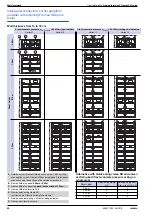
Page 23: ...dth 1 35m Panel width 0 90m Panel width 0 75m Panel width 0 60m Panel width 0 45m Panel width 0 30m Observe the following points Position the universal walings in such a way that at most two single form tie panels without brac ing are placed side by side Always position the universal walings in the bot tom waling profile Max closure width between the single form tie panels 15 cm with Framax multi ...

Page 24: ...24 999811202 04 2019 Wall formwork User Information Framed formwork Framax Xlife plus Corner configuration with single form tie panels example 9 2 0 8112 90 2 ...

Page 25: ...ttach using the Framax wedge clamp using the Framax universal fixing bolt and Super plate A Framax universal waling 1 50m B Framax wedge clamp C Framax multi function clamp D Framax Xlife plus panel E Cross profile acting as a support for the universal waling Framax universal waling Permitted moment for vertical stacking 5 0 kNm Due to the permitted tensile load of 14 kN in the waling profile even...

Page 26: ...uick acting clamp RU C Framax multi function clamp D Framax universal waling E Framax wedge clamp Framax multi function clamp permitted tensile force 15 0 kN permitted shear force 9 0 kN permitted moment 0 9 kNm Values apply only when mounted on profile contact surface on the profile Framax quick acting clamp RU permitted tensile force 15 0 kN permitted shear force 6 0 kN permitted moment 0 5 kNm ...

Page 27: ...ing platform with single brackets Fra max bracket 90 the universal waling is not necessary Formwork height 435 and 450 cm Formwork height 465 480 and 495 cm Formwork height 540 cm Formwork height 570 and 585 cm 9 2 01 8112 33 270 135 9 2 0 8112 34 2 270 135 30 45 9 2 01 8112 35 270 135 60 90 98112 236 01 270 270 98112 237 02 270 270 30 45 ...

Page 28: ...rd universal waling at the first and the second panel joint is only needed if intermediate platforms are to be used Formwork height 735 750 and 765 cm The third universal waling at the first and the second panel joint is only needed if intermediate platforms are to be used 98112 237 01 270 270 60 135 270 270 135 30 45 98112 239 02 270 270 135 60 90 9 2 01 8112 39 ...

Page 29: ...panel joint is only needed if intermediate platforms are to be used with Framax quick acting clamp RU Formwork height 300 and 315 cm Universal waling only needed if pouring platforms are to be used Formwork height 330 345 360 and 405 cm Formwork height 435 and 450 cm 98112 238 01 270 270 270 98112 248 01 270 30 45 98112 249 01 270 60 135 98112 250 02 270 135 30 45 ...

Page 30: ...ation Framed formwork Framax Xlife plus Formwork height 465 cm Formwork height 480 and 495 cm Formwork height 540 cm Formwork height 570 and 585 cm 98112 250 01 270 135 60 9 01 8112 251 270 135 75 90 98112 252 01 270 270 98112 253 02 270 270 30 45 ...

Page 31: ...The third universal waling at the first panel joint is only needed if inter mediate platforms are to be used Formwork height 705 and 720 cm The third universal waling at the first and the second panel joint is only needed if intermediate platforms are to be used 9 01 8112 253 270 270 60 90 98112 254 01 270 270 135 270 270 135 30 45 98112 255 02 ...

Page 32: ...ormwork Framax Xlife plus Formwork height 735 cm The third universal waling at the first and the second panel joint is only needed if intermediate platforms are to be used Formwork height 750 and 765 cm 98112 255 01 270 270 135 60 9 01 8112 256 270 270 135 75 90 ...

Page 33: ...ormwork height 360 and 375 cm When using a lightweight pouring platform with single brackets Fra max bracket 90 the universal waling is not necessary Formwork height 390 and 405 cm When using a lightweight pouring platform with single brackets Fra max bracket 90 the universal waling is not necessary 98112 257 01 270 270 270 9 01 8112 306 330 30 45 9 0 8112 306 2 330 60 75 ...

Page 34: ...ramed formwork Framax Xlife plus Formwork height 420 and 465 cm Formwork height 495 and 510 cm Formwork height 525 540 and 555 cm Formwork height 600 cm 98112 306 03 330 90 135 9 0 8112 306 4 330 135 30 45 9 0 8112 306 6 330 135 60 90 98112 306 07 330 270 ...

Page 35: ... universal waling is not needed if a light pouring platform made of single brackets Framax bracket 90 is to be used Formwork height 660 cm Formwork height 690 and 705 cm The third universal waling is needed only if intermediate platforms are to be used 30 45 9 0 8112 306 8 330 270 98112 306 09 330 330 98112 306 10 330 330 30 45 ...

Page 36: ... Information Framed formwork Framax Xlife plus Formwork height 720 735 and 750 cm The third universal waling is needed only if intermediate platforms are to be used Formwork height 795 cm 9 8112 306 11 330 330 60 90 98112 306 12 330 330 135 ...

Page 37: ... clamp RU Formwork height 360 and 375 cm Universal waling only needed if pouring platforms are to be used Formwork height 390 405 420 and 465 cm Formwork height 495 and 510 cm Formwork height 525 540 and 555 cm 98112 306 13 330 30 45 98112 306 14 330 60 135 98112 306 15 330 135 30 45 9 8112 306 16 330 135 60 90 ...

Page 38: ... Formwork height 600 cm Formwork height 630 and 645 cm Formwork height 660 cm Formwork height 690 and 705 cm The third universal waling is needed only if intermediate platforms are to be used 98112 306 17 330 270 98112 306 18 330 270 30 45 98112 306 19 330 330 98112 306 20 330 330 30 45 ...

Page 39: ... Xlife plus Wall formwork 39 999811202 04 2019 Formwork height 720 735 and 750 cm The third universal waling is needed only if intermediate platforms are to be used Formwork height 795 cm 9 8112 306 21 330 330 60 90 98112 306 22 330 330 135 ...

Page 40: ...cm 90 degree corners and Acute obtuse angled corners A Framax Xlife plus form tie 20 0 B Framax Xlife plus form tie nut I 20 0 C Framax Xlife plus form tie nut 20 0 D Framax Xlife plus distance protector E Form tie sleeve inside the framed formwork panel 9 2 0 8112 44 1 B E A 9 2 0 8112 01 7 D C E A 9 2 0 8112 01 3 D Wall thicknesses in 0 5 cm increments Framax Xlife plus form tie 20 0 15 30cm 15 ...

Page 41: ...urning the ball pin makes it easier to push it away C Stop cylinder A Spring clip B Ball pin C Stop cylinder 98112 242 01 A B 98112 242 03 C A C 98112 242 02 B A 30 0 25 0 20 0 15 0 B 40 0 35 0 30 0 25 0 A Framax Xlife plus form tie 15 30cm B Framax Xlife plus form tie 25 40cm C Stop cylinder D Marking groove on the stop cylinder A Framax Xlife plus form tie 15 30cm C Stop cylinder D Marking groov...

Page 42: ...e framed formwork panel The hook of the form tie nut engages in the recess of the form tie sleeve Push the centring disc in and at the same time turn it through 180 Position of the centring disc Centring disc engages Form tie nut is fixed in place Mounting the Form tie nut 20 0 Position the form tie nut into the form tie sleeve of the framed formwork panel and screw it on A Framax Xlife plus dista...

Page 43: ...ra max Xlife plus ratchet or an impact wrench Temporarily store the Framax Xlife plus form tie in the distance protector E Framax Xlife plus distance protector C Framax Xlife plus form tie 20 0 D Framax Xlife plus ratchet 1 2 SW24 L H Spring clip Check that the spring clip is installed Spraying the conical part of the form tie with release agent makes it easier to detach the form tie from the conc...

Page 44: ...ife plus fair faced concr cone 87mm with built in magnets to the form tie sleeves of the panels On the side of the holding formwork form tie nut seal the fair faced concrete cone with a Sealing disk 43 self adhesive Close up Install the form tie and the distance protector see the section headed Tying the panels A Framax Xlife plus form tie nut I 20 0 B Framax Xlife plus parking bolt If the parking...

Page 45: ...rm tie sleeve Turn the lock of the reducer through 180 Reducer is locked in position Position of the lock For more information on making watertight form tie points see the Doka form ties for spe cial requirements User Information booklet A Framax Xlife plus reducer I 20 0 B Tie rod 20 0mm C Super plate 20 0 B D Plastic tube 26mm E Universal cone 26mm F Form tie sleeve inside the Framax Xlife plus ...

Page 46: ...e Framax head anchor 15 40cm directly above the form tie points of the Framax Xlife plus panel Telescope the Framax head anchor 15 40cm to the desired length a wall thickness and fix it in the relevant hole with a pin and spring cotter a 15 40 cm Example panel of max 0 90m vertically stacked b max 0 90 m Example Framax Xlife plus panel 3 30m c 3 30 m NOTICE 2 Framax head anchors 15 40cm must be mo...

Page 47: ... for fair faced concrete qual ity Use the Framax Xlife plus cone spanner to remove the Framax Xlife plus fair faced concr cone 87mm Close the open form tie point with a Framax Xlife plus fair faced concr plug 87mm The concrete plug is glued into place with standard concrete adhesive Framax Xlife plus plug 38mm Framax Xlife plus plug 24mm Framax Xlife plus fair faced concr plug 87mm fire resistant ...

Page 48: ...plug as the adhesive is compressed with Framax Xlife plus screw plug 25mm by glueing in Fibre concrete plug 24mm with moulding mortar fire resistant sound insulating watertight for compatibility with drinking water see the section headed Drinking water compatible seal G Framax Xlife plus screw plug 25mm W Water side NOTICE Material temperature of the screw at time of installation at least 10 C G W...

Page 49: ... Push the second fibre concrete plug into the adhe sive and compress the adhesive Use a spatula to remove the excess adhesive Product recommendation A Framax Xlife plus plug 24mm with hole J Fibre concrete plug 24mm K Epoxy resin adhesive Mapefix EP epoxy resin adhesive Epoxy resin based 2 component adhesive for structural loads The surface must be free of dust and oil Application temperature min ...

Page 50: ...m tie hole to obtain a surface that is drinking water com patible drinking water tanks for example usable in all sealing situations shown here Example Framax Xlife plus screw plug 25mm On the water wetted side install the plug recessed at least 3 mm Apply SikaDur 31 DW and smooth the compound off flush with the surface Product recommendation A Framax Xlife plus plug 24mm with hole L M Bed moulding...

Page 51: ...User Information Framed formwork Framax Xlife plus Wall formwork 51 999811202 04 2019 ...

Page 52: ...nsion anchor can be made using a tie rod and Star grip nut 15 0 G A Framax alu closure Framax fitting timber B Framax multi function clamp C Framax Xlife plus panel A Framax alu closure Framax fitting timber B Framax adjustable clamp C Framax Xlife plus panel 9 2 01 8112 68 98112 268 02 A B C 98112 268 03 A B C Framax adjustable clamp Permitted tensile force 10 0 kN A Framax moulded timber 27mm fo...

Page 53: ...e made using universal fixing bolts super plates Outside formwork Right angled outside corners can be formed in any of the following ways Framax outside corner A Framax Xlife plus outs corner 10 10cm B Framax Xlife universal panel C Note For details regarding extra inter panel connections on outside corners for increased tensile loads see Inter panel connections for increased tensile loads 98112 3...

Page 54: ... 20 0 J Inter panel connection see the section headed Inter panel con nection corner gangform outside with adjoining Framax Xlife plus panel 9 2 01 8112 78 9 2 0 8112 78 2 a 2 b1 c1 b 2 c 2 a1 B C D D E E A F G H J J Wall thickness a Panel width b 15 cm 0 45m 45 cm 15 30 cm 0 60m 60 cm 30 40 cm 0 75m 75 cm Closure width c panel width b cm 30 cm wall thickness a cm When there is a closure on both s...

Page 55: ...0m 0 75m D Framax Xlife plus panel no panel with a width of 1 35m E Framax Xlife plus panel F Closure 0 15 cm Framax alu closure Framax fitting timber G Framax multi function clamp H Tie rod system Framax Xlife plus 20 0 J Inter panel connection see the section headed Inter panel con nection corner gangform outside with adjoining Framax Xlife plus panel 98112 325 2 0 98112 325 3 0 a 2 b1 c1 b 2 c ...

Page 56: ...gform A Framax Xlife plus outs corner 10 10cm B Framax Xlife plus panel E Squared timber 10 10 cm A Framax Xlife plus outs corner 10 10cm B Framax Xlife plus panel C Clamping bolt 15 0 Install the bottom clamping bolt and provi sionally secure the outside corner to the panel with 2 quick acting clamps RU This makes the rest of the clamping bolts eas ier to install A Framax Xlife plus outs corner 1...

Page 57: ...el with a width of 1 35m E Framax Xlife plus panel F Closure 0 15 cm Framax alu closure Framax fitting timber G Framax multi function clamp H Tie rod system Framax Xlife plus 20 0 I Framax universal fixing bolt Super plate 15 0 J Inter panel connection see the section headed Inter panel con nection corner gangform outside with adjoining Framax Xlife plus panel 9 2 01 8112 77 9 2 0 8112 77 2 B D D ...

Page 58: ...9 1 0 8112 3 7 5 G D E 9 11 01 8112 3 A B C F 9 1 01 8112 3 2 9 11 0 8112 3 2 9 1 0 8112 3 2 2 9 1 0 8112 3 2 4 9 11 0 8112 3 3 9 11 0 8112 3 4 9 1 0 8112 3 2 3 9 1 0 8112 3 2 5 A Outside corner Framax Xlife plus outs corner 10 10cm Fra max outside corner Framax Xlife universal panel Inter panel connection see the section on the outside corner used B Framax Xlife plus panel 0 45m or 0 60m C Framax...

Page 59: ... 3 4 9 1 0 8112 3 3 2 9 0 8112 313 4 9 1 0 8112 3 4 2 9 1 0 8112 3 4 4 9 1 0 8112 3 3 3 9 0 8112 313 5 9 1 0 8112 3 4 3 A Outside corner Framax Xlife plus outs corner 10 10cm Fra max outside corner Framax Xlife universal panel Inter panel connection see the section on the outside corner used B Framax Xlife plus panel 0 75m with Framax Xlife plus outside corner 10 10cm 0 60m C Framax Xlife plus pan...

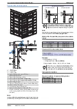
Page 60: ... inside corner 30 30cm or Framax Xlife inside corner B Framax Xlife plus panel 0 75m 0 90m C Framax Xlife plus panel max width of 0 45m D Framax Xlife plus panel max width of 0 90m E Closure 0 15 cm Framax alu closure Framax fitting timber F Framax multi function clamp G Tie rod system Framax Xlife plus 20 0 H Multi purpose waling WS10 Top50 I Framax wedge clamp J Inter panel connection see the se...

Page 61: ...lus inside corner 30 30cm or Framax Xlife inside corner B Framax Xlife plus panel 0 90m C Framax Xlife plus panel max width of 0 30m D Framax Xlife plus panel max width of 0 90m E Closure 0 15 cm Framax alu closure Framax fitting timber G Tie rod system Framax Xlife plus 20 0 H Multi purpose waling WS10 Top50 I Framax wedge clamp J Inter panel connection see the section headed T junction Inter pan...

Page 62: ... Framax fitting timber D Doka tie rod system 20 0 E Framax Xlife plus panel F Doka tie rod system 20 0 A form tie is only needed in this position if a Framax Xlife plus panel with a width of 1 35m is used as a connecting panel G G Connecting panel H Tie rod system Framax Xlife plus 20 0 I Framax multi function clamp J Framax quick acting clamp RU Permitted fresh concrete pressure 80kN m 98112 279 ...

Page 63: ... 3 J 9 42 02 8112 3 I K K 9 43 02 8112 3 I I 9 42 03 8112 3 9 43 03 8112 3 H 9 42 04 8112 3 9 43 04 8112 3 Permitted fresh concrete pressure σhk max 80 kN m2 hydrostatic 60 kN m2 acting on whole area 0 60m 1 35m 2 70m 3 30m A Framax Xlife plus panel 0 75m or 0 90m B Framax Xlife plus panel max width of 0 45m C Framax Xlife plus panel 0 90m D Framax Xlife plus panel max width of 0 30m E Closure 0 1...

Page 64: ...angular ledge of course a 20 mm with the Framax triangular ledge Where outside corners are formed using the Framax outside corner the Quick acting clamps used for the interconnection mean that the Framax triangular ledge has to be used a 20 mm A Framax frontal triangular ledge or Framax triangular ledge 2 70m B Framax universal fixing bolt C Super plate 15 0 D Framax Xlife universal panel E Framax...

Page 65: ...e corner I C Framax hinged outside corner A galv D Framax hinged outside corner A 98112 3 1 2 3 0 98112 334 04 a a b b A 98112 334 02 a a b b B 98112 334 03 a a C 98112 334 01 a a b b D bmax panel width closure Permitted fresh concrete pres sure σhk max 100 cm 82 5 kN m2 hydrostatic 80 cm 50 kN m2 acting on whole area 70 cm 60 kN m2 60 cm 70 kN m2 52 cm 80 kN m2 A Hinged outside corner Framax hing...

Page 66: ... tensile loads see Inter panel connections for increased tensile loads Hinged outside corner A 60 135 a 30 cm Framax Xlife plus panel 0 60m 2 Framax Xlife plus panel 1 35m 4 Framax Xlife plus panel 2 70m 6 Framax Xlife plus panel 3 30m 8 NOTICE With closures provide additional universal walings in accordance with the section headed Length adjustment using closures Panel height Number of clamps 0 6...

Page 67: ...s tie rods H from the outside A Framax hinged outside corner A B Framax hinged inside corner I C Framax Xlife plus panel 0 45m D Framax Xlife plus panel max width 0 60m E Framax Xlife plus panel F Closure 9 cm G Framax multi function clamp H Tie rod system Framax Xlife plus I Framax universal waling 0 90m J Framax wedge clamp K Inter panel connection see the section headed Inter panel connection c...

Page 68: ...rner gang form outside with hinged corner with adjoining Framax Xlife plus panel 98112 337 1 0 H 98112 337 2 0 a a B C B E D K C E D K 90 F max b max b B Framax hinged inside corner I D Framax Xlife plus panel max width 0 60m E Framax Xlife plus panel F Closure 8 cm G Framax multi function clamp H Tie rod system Framax Xlife plus I Framax universal waling 0 90m J Framax wedge clamp K Inter panel c...

Page 69: ... 3 7 5 G D E 9 11 01 8112 3 A B C F 9 1 01 8112 3 2 9 11 0 8112 3 2 9 1 0 8112 3 2 2 9 1 0 8112 3 2 4 9 11 0 8112 3 3 9 11 0 8112 3 4 9 1 0 8112 3 2 3 9 1 0 8112 3 2 5 A Hinged outside corner Framax hinged outside corner A or Framax hinged inside corner I Inter panel connection see the table Number of con nectors needed in the hinged outside corner B Framax Xlife plus panel 0 30m 0 75m C Framax Xl...

Page 70: ...70 999811202 04 2019 Wall formwork User Information Framed formwork Framax Xlife plus ...

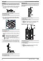
Page 71: ...e uses stripping spindles Entire shaft formwork unit is lifted and reset in one piece with lifting hooks and four part lifting chain Two different types of stripping spindle can be used for setting up and stripping the formwork Framax stripping spindle I with ratchet Framax stripping spindle I Required number of Framax quick acting clamps RU Note In order to obtain the full available stripping pla...

Page 72: ...373947 Mounting the Framax stripping spindles I These mounting instructions apply to both Stripping spindles I and Stripping spindles I with ratchet 1 Pull out the U bolt from the stripping spindle 2 Place the stripping spindle on the centring stud of the stripping corner 3 Twist the stripping spindle clockwise until fully engaged 4 Position the ratchet or spindle nut between the holes in the push...

Page 73: ...0mm through one of the holes in the spindle nut Setting up Twist the spindle nut clockwise Stripping Twist the spindle nut anti clockwise Lifting by crane A Tie rod 15 0mm B Weldable coupler 15 0 C Ratchet D Change over lever A Tie rod 15 0mm B Spindle nut B Tr706 202 01 A D C Tr750 204 01 B A β max 15 A Framax lifting hook B Four part lifting chain e g Doka 4 part chain 3 20m The crane hook on th...

Page 74: ...ach other in the shaft bracing with universal walings is required Observe the following points Position the universal walings in such a way that at most two single form tie panels without brac ing are placed side by side Always position universal walings at the second inter panel joint away from each corner Always position the universal walings in the bot tom waling profile Max closure width betwe...

Page 75: ...ramax Xlife plus outs corner 10 10cm Fra max outside corner Framax Xlife universal panel C Framax Xlife plus panel 0 45m 0 60m 0 75m D Framax Xlife plus panel max width of 0 90m F Closure 0 15 cm Framax alu closure Framax fitting timber G Framax multi function clamp H Framax universal waling I Framax wedge clamp J Tie rod system Framax Xlife plus 20 0 K Inter panel connection see the section heade...

Page 76: ...e corner Framax Xlife plus outs corner 10 10cm Fra max outside corner Framax Xlife universal panel Inter panel connection see the section on the outside corner used B Framax Xlife plus panel 0 45m or 0 60m C Framax Xlife plus panel max width of 0 90m D Framax quick acting clamp RU or Framax multi function clamp for a closure E Framax Xlife plus form tie 20 0 F Framax universal waling 2 Framax wedg...

Page 77: ...Fra max outside corner Framax Xlife universal panel Inter panel connection see the section on the outside corner used B Framax Xlife plus panel 0 60m or 0 75m C Framax Xlife plus panel max width of 0 90m D Framax quick acting clamp RU or Framax multi function clamp for a closure E Framax Xlife plus form tie 20 0 F Framax universal waling 2 Framax wedge clamps D E 9 4 01 8112 3 7 A B C 9 48 01 8112...

Page 78: ...mpacting concrete NOTICE For use of self compacting concrete SCC note the following For bracing across the entire width of the shaft use a single full length waling instead of two or more universal walings A Self Compacting Concrete SCC B Multi purpose waling WS10 Top50 C Framax wedge clamp A C B 9 54 03 8112 3 ...

Page 79: ...rk height as a tension link between the panels However where increased tensile loads need to be sustained near outside corners and stop ends extra clamps are needed Near stop ends a up to 40 cm b 1 35 m X1 1 additional clamp Near outside corners a up to 40 cm b 1 35 m X1 1 additional clamp Wall thicknesses up to 40 cm For each panel joint up to 1 35 m 1 extra clamp 9 01 8112 264 b X1 a 98112 278 0...

Page 80: ...mounted using universal fixing bolts and Super plates 15 0 fixed through the cross boreholes in the panels with stop end waler ties The stop end waler ties make it possible to form stop ends continuously from wall thicknesses of 15 cm to 45 cm a 15 to 45 cm A Framax universal waling B Framax universal fixing bolt Super plate 15 0 C Framax Xlife plus panel panel width 0 30m D Doka tie rod system Fr...

Page 81: ...s of Framax stop end waler ties On a vertically placed panel On a horizontally placed panel G Cross profile H Cross borehole plate C Twin pins D Screwjack clamp E Star grip nut 98112 200 03 G 98112 202 01 H 9764 468 03 15 20 30 35 40 45 25 cm E D C Upright panels Panel height 2 70m 3 30m 2 3 Horizontal panels Panel width 0 30m 0 60m 0 75m 1 35m 1 2 Panels longside vertical Number of stop end waler...

Page 82: ...ls of up to 60 cm thick Stop ends with joint sealing tapes Universal panel 0 90m 4 Universal panel 1 35m 4 Universal panel 2 70m 8 Universal panel 3 30m 10 A Framax Xlife universal panel 0 90m B Framax universal fixing bolt Super plate 15 0 C Framax Xlife plus panel panel width 0 30m 9 20 0 8112 1 2 98112 201 01 X C D E F G H A B D C B A A B C Combination Wall thickness X A with H to A 16 to 51 cm...

Page 83: ...Xlife plus 20 0 C Timber brace A Framax Xlife plus panel B Tie rod system Framax Xlife plus 20 0 A Framax Xlife plus panel B Tie rod system Framax Xlife plus 20 0 C Framax multi function clamp D Squared timber E Timber brace 98112 225 01 C B A 98112 225 02 A B 98112 225 03 E D C A B C Framax wedge clamp D Framax universal waling 0 90m E Super plate 15 0 Framax universal fixing bolt 10 25cm H Tie r...

Page 84: ...5 0 Tie rod 15 0 H Tie rod system Framax Xlife plus 20 0 I Squared timber J Framax fitting timber 10x12cm K Rod connector 15 0 L Framax stop end tie M Super plate 15 0 Star grip nut 15 0 G Tie rod 15 0mm Lmin 0 40 m N Framax Xlife plus panel 0 45m A 9 309 01 8112 a a E C I F D G M B J N H 9 309 02 8112 J B N D G K L F M C I H A Framax Xlife plus inside corner 30 30cm or Framax Xlife inside corner ...

Page 85: ...idth of opening l length of plank a minus 12 cm s plank width wall thickness Assembly Place the box out clamps on the ground fit boards into them and tighten the star grip nuts Fasten the box outs to the wall formwork with boards 10 3 cm and nails Brace vertically and horizontally with suitable floor props as statically required A Box out clamp B Framax Xlife plus panel C Doka floor prop D Plank w...

Page 86: ...supported by at least 2 plumbing accessories Example Where the formwork height is 7 20 m the fol lowing are needed for every 5 40 m wide gang form 2 panel struts 340 4 panel struts 540 WARNING Risk of the formwork tipping over Formwork panels must be held stable in every phase of construction work Observe all applicable safety rules If high wind speeds are likely and when work finishes for the day...

Page 87: ...ex 60 550 A Doka express anchor 16x125mm B Doka coil 16mm Characteristic cube compressive strength of the con crete fck cube min 15 N mm2 C12 15 grade concrete Follow the Fitting Instructions Required safe working load of alternative anchors for footplates Rd 20 3 kN Fpermissible 13 5 kN Follow the manufacturers applicable fitting instruc tions 9727 339 01 A B a 9727 343 01 b 9745 214 01 c d d TR6...

Page 88: ...rox 60 Follow the directions in the Eurex 60 550 User Information booklet Type Length extended L m Plumbing strut Eurex 60 550 A Extension Eurex 60 2 00m B Coupler Eurex 60 C Connector Eurex 60 IB D Plumbing strut shoe Eurex 60 EB E Adjusting strut 540 Eurex 60 IB F Prop head EB G Weight kg 1 3 79 5 89 1 1 1 1 2 91 1 2 5 79 7 89 1 1 1 1 1 2 112 4 3 7 79 9 89 1 2 1 1 1 2 133 7 4 7 22 11 42 2 1 1 1 ...

Page 89: ...as a width of 2 70 m 2 70m 1 35m Mounting the lifting adapter onto the platform Use a Connecting pin 10cm and Spring cotter 5mm to mount the lifting adapter to the platform Precondition for use Observe all applicable safety rules Engage pouring platforms only to formwork struc tures of adequate stability to ensure that the expected loads can be taken Make sure that the formwork gang is sufficientl...

Page 90: ... platform is now secured against accidental lift out a 13 cm The level of the floor planking is 13 cm below the top edge of the formwork This means that there is a boundary on the side facing the formwork Lifting the platform off the formwork Attach a four part lifting chain to the platform and raise it When the platform is raised by the four part lifting chain on the safety hook the platform is a...

Page 91: ...m 1 35m A Integrated ladder connection on the Xsafe plus platform C Spring cotter 5mm The groove in the ladder pin B must be engaged in the hole of the ladder connec tion A The ladder must be secured with Spring cotters 5mm C A Xsafe plus ladder starter piece B Waling profile of the Framax Xlife plus panel C Spring cotter of the Xsafe plus ladder starter piece 976 450 04 4 976 450 05 4 C A 976 04 ...

Page 92: ...ion Put both side stops into position Close the decking with the tilt back board Permitted service load 1 5 kN m2 150 kg m2 Load Class 2 to EN 12811 1 2003 NOTICE It is not permissible to lay the formwork down flat together with the pouring platform Planks can be used to bridge decking to decking gaps up to 50 cm for length adapta tion Minimum plank overlap 25 cm The pouring platform cannot be ins...

Page 93: ...secured against accidental lift out Lifting the platform off the formwork Attach a four part lifting chain to the pouring platform and raise it When the pouring platform is raised by the four part lifting chain on the safety hook the platform is auto matically unlocked Transporting stacking and storing a 268 cm b 295 cm c 10 x 18 7 cm d 31 cm e approx 218 cm f 142 cm g 50 cm A Safety hook Do a sig...

Page 94: ...position Unfold the bracket A and latch it into place Lifting the platform onto the formwork Attach a four part lifting tackle e g Doka 4 part chain 3 20m to the pouring platform and hoist it towards the formwork Permitted service load 1 5 kN m2 150 kg m2 Load Class 2 to EN 12811 1 2003 NOTICE It is not permissible to lay the formwork down flat together with the pouring platform Planks can be used...

Page 95: ...tructure suitable sideguards must be placed across exposed end of platform zones Note The plank and board thicknesses given here comply with the C24 category of EN 338 Observe all national regulations applying to deck boards and guard rail boards Side handrail clamping unit T Assembly Fasten the clamping component to the floor planking of the pouring scaffold using the wedge clamping range 4 to 6 ...

Page 96: ...or mounting the couplers and scaffold tubes Possible ways of fixing to upright panels Note Where brackets need to be fixed to the middle cross profile of upright Framax Xlife universal panels 2 70m and 3 30m 2008 models onward this can also be done in the left hand borehole Preconditions for use Observe all applicable safety regulations Only fix the pouring platform onto formwork construc tions th...

Page 97: ...2 to 43 cm Working from below push a Toeboard holder XP 1 20m onto the Handrail post XP 1 20m Push the Handrail post XP 1 20m into the post hold ing fixture on the Railing clamps XP until the locking mechanism engages Fix guard rail boards to the handrail post plates with nails diam 5 mm Handrail clamp S In the cross profile Anti liftout guard A Framax bracket 90 B Spring cotter C Wedge bolt RA 7 ...

Page 98: ... bolt on the Adapters XP until the spring snaps into place allow for overlap between protective gratings and or guard rail boards Tilt the safety barrier outward The safety bolt now automatically drops and secures the tilted barrier unit Types of safety barrier a 143 cm b 103 cm A Handrail post XP 1 20m B Framax adapter XP C Protective grating XP or guard rail boards F Safety bolt 98112 221 01 A B...

Page 99: ... 5 mm Lifting by crane When lifting gang forms together with opposing guard rails assembled from the Edge protection system XP remember the following points The guard rails must be in the vertical position when the gang form is raised or laid down Elastic deformation of the guard rails may occur because the 4 part chain is resting against the pro tective grating or guard rail boards while the gang...

Page 100: ...rmwork e g for cleaning the form facing Picking up from the cleaning position Repositioning the upright gang form A Form ply side Dynamic pressure q kN m2 0 2 0 6 1 1 1 3 Permitted support centres Protective grating XP 2 5 m Guard rail board 2 4 x 15 cm 1 9 m Guard rail board 3 x 15 cm 2 7 m Guard rail board 4 x 15 cm 3 3 m Dynamic pressure q kN m2 0 2 0 6 1 1 1 3 Permitted cantilever Protective g...

Page 101: ...ghten the Screw in cone 15 0 b Offset approx 1 0 cm so that the formwork can be tightened against the wall slab Position the holding formwork Lower the opposing formwork on to the support angle by crane C Wall formwork support angle F Opposing formwork G Holding formwork H Façade scaffolding e g Working scaffold Modul Max load 2000 kg Wall formwork support angle NOTICE Static verification is requi...

Page 102: ...en the formwork against the wall slab Fit the anchors Detach the gang form from the crane E Wedge F Opposing formwork Before disconnecting from the crane Do not disconnect the panel from the crane until a large enough number of form ties have been installed to keep it safely in the upright 9 0 8112 320 4 E F ...

Page 103: ...taching connectors to the formwork Place the Connector XS Wall formwork against the frame profile near the top of the formwork Fasten the Connector XS Wall formwork to the frame profile using two Quick acting clamps RU Place a Connector XS wall formwork against the frame profile near the bottom of the formwork Fasten the Connector XS Wall formwork to the frame profile using two Quick acting clamps...

Page 104: ...with a linch pin in the front position a for one single ladder in the rear position b in the telescoping zone for 2 ladders Animation https player vimeo com video 274427263 Mount the Securing barrier XS to the ladder with fix ing hooks and wing nuts The components needed for mounting the Securing barrier XS are captively attached to it Ladder system XS for heights above 3 75 m Telescoping ladder e...

Page 105: ...y Attach the Ladder cage exit XS the bottom of the cage must always be at the same height as the plat form The safety latches prevent the cage from being accidentally lifted out Attach the Ladder cage XS to the next available rung Attach further ladder cages in each case to the next available rung A System ladder XS 4 40m B Ladder extension XS 2 30m C Screws width across 17 mm NOTICE Always observ...

Page 106: ...ng clamp RU 4 4 6 or Fixing clamp XS Framax1 2 2 3 System ladder XS 4 40m 1 1 1 Ladder extension XS 2 30m 0 1 2 Ladder cage Formwork height 2 70 3 15 m 3 15 4 05 m 4 05 5 40 m 5 40 6 60 m 6 60 7 65 m 7 65 8 10 m Ladder cage exit XS 2 1 1 1 1 1 1 Securing bar rier XS 2 1 1 1 1 1 1 Ladder cage XS 1 00m 2 0 1 2 3 4 5 Basic rule The number of Connectors XS wall formwork and ladder components is shown ...

Page 107: ...amed formwork can be detached from the con crete using the Framax stripping tool 1 Secure the panel or gang form to prevent it from falling over e g by attaching it to the crane or securing it with panel struts 2 Position the Framax stripping tool into a cross bore hole of the framed formwork 3 Lever the framed formwork away from the con crete 98112 296 01 98112 296 02 ...

Page 108: ...t be placed over a cross profile Two upright panels Always place the Framax lifting hook over one of the centre profiles or welded on metal plates to prevent it from sliding from side to side Max load as 2 part chain Up to spread angle of 30 β 2400 kg Follow the directions in the Operating Instruc tions Max load Spread angle β up to 30 1000 kg 2200 lbs Framax lifting hook Spread angle β up to 7 5 ...

Page 109: ...ng and repositioning the panels Before lifting Remove any loose items from the form work and platforms or secure them firmly Lift the gang form to its new location guide with tag lines if necessary Framax 3 in 1 pole tool The Framax 3 in 1 pole tool has three handy func tions Do a sight check to make sure that there is a secure form fit between the lifting hook and the frame profile The handle mus...

Page 110: ...s without inserting Framax Xlife plus stacking cones 2 cones per layer first Exception Stacking cones are not required if the stack is lifted using the Framax transport gear Panels with Form tie nuts I 20 0 Panels with no form tie nuts A Framax Xlife plus stacking cone I B Framax Xlife plus stacking cone C Framax Xlife plus form tie nuts I 20 0 A Framax Xlife plus stacking cone or Framax Xlife plu...

Page 111: ...rt chain 3 20m The Doka 4 part chain 3 20m is a multi functional sling ing means used with the integrated eye hooks for hoisting formwork platforms and multi trip packaging con tainers For further information see the section headed Lift ing by crane used in conjunction with Framax transport bolts for hoisting stacks of panels and individual panels The Doka 4 part chain 3 20m can be adjusted to the...

Page 112: ...own Hoisting bundled stacks of panels Lifting panels off the stack Max load 800 kg Framax transport bolt Framax transport bolts manufactured until 2015 with a given load capacity of 500 kg are also capable of a carrying capacity of 800 kg Follow the directions in the Operating Instruc tions 9259 201 01 A B B A 98112 283 02 98112 283 01 B A A Framax transport bolt B Doka 4 part chain 3 20m C Square...

Page 113: ...your site Multi trip packaging such as containers stacking pal lets and skeleton transport boxes keep everything in place on the site minimise time wasted searching for parts and streamline the storage and transport of sys tem components small items and accessories Max load 700 kg 1540 lbs Permitted imposed load 3150 kg 6950 lbs NOTICE Multi trip packaging items that each contain very different lo...

Page 114: ...The forks can be inserted under either the broadside or the narrowside of the containers Max load 1500 kg 3300 lbs Permitted imposed load 7850 kg 17305 lbs NOTICE Multi trip packaging items that each contain very different loads must be stacked with the heaviest ones at the bottom and the lightest ones at the top Rating plate must be in place and clearly legible A Slide bolt for fixing the partiti...

Page 115: ...ermitted imposed load 5900 kg 12980 lbs NOTICE Multi trip packaging items that each contain very different loads must be stacked with the heaviest ones at the bottom and the lightest ones at the top Rating plate must be in place and clearly legible Outdoors on the site Indoors Floor gradients of up to 3 Floor gradients of up to 1 2 6 It is not allowed to stack empty pallets on top of one another N...

Page 116: ...wside of the containers Bolt on castor set B The Bolt on caster set B turns the stacking pallet into a fast and manoeuvrable transport device Suitable for drive through access openings 90 cm The Bolt on caster set B can be mounted to the follow ing multi trip packaging items Doka accessory box Doka stacking pallets Max load 1000 kg 2200 lbs Permitted imposed load 5530 kg 12191 lbs NOTICE Multi tri...

Page 117: ...User Information Framed formwork Framax Xlife plus Wall formwork 117 999811202 04 2019 ...

Page 118: ...side horizontal Number of Framax head anchors 1 35x3 30m 3 0 30 up to 0 90x3 30m 2 0 30 up to 1 35x2 70m 2 Framax Xlife plus panel longside vertical Number of Framax head anchors 1 35x1 35m 1 0 30 up to 0 90x3 30m 1 Framax head anchor Permitted tensile force 10 kN Permitted compressive force 10 kN A Framax Xlife plus panel 0 90x2 70m B Framax head anchor C Tie rod system Framax Xlife plus D Formwo...

Page 119: ...work With their modular design concept these crane inde pendent automatic climbing formwork systems provide an efficient solution for every type of structure The formwork and climbing scaffold are linked together as a single unit which can be lifted and reset hydrauli cally A Climbing bracket MF240 B Travelling unit MF C Suspended platform MF75 5 00m D Framax bracket 90 E Framax Xlife plus panel F...

Page 120: ...lso enable the sturdy Framax Xlife plus panels to be used as single sided wall formwork Supporting construction frame Universal F Supporting construction frame Variable A Doka folding platform B Panel strut C Framax pouring platform D Framax Xlife plus panel Follow the directions in the Folding platform K and Climbing formwork K User Informa tion booklets 9727 448 01 B C D A Follow the directions ...

Page 121: ... little assembly work is needed system accessories for closure gaps and corner transitions Safe working high safety as side and end guards are integrated in the platform integrable ladder system An economical solution its perfect stackability cuts storage and freight costs no universal walings needed for bracing the panels in vertically stacked configurations simplified planning from using a singl...

Page 122: ...r pouring Remove any blobs of concrete from the back face of the formwork using water without any added sand Immediately after stripping out the formwork Clean the formwork with a high pres sure washer and a concrete scraper Do not use any chemical cleaning agents Cleaning high formwork Provide a service tower at a suitable cleaning location Wheel around scaffold DF up to a formwork height of 3 90...

Page 123: ...g sleeve cleaner on to the Framax Xlife plus ratchet and turn the cleaner in the sleeve A Blade for dealing with heavy soiling B Blade for dealing with slight soiling NOTICE Do not use pointed or sharp objects wire brushes abrasive disks or cup brushes 9727 015 Tr741 200 02 Tr741 200 01 A B 9727 009 A Framax Xlife plus anchoring sleeve cleaner B Framax Xlife plus ratchet 1 2 SW24 L C Form tie slee...

Page 124: ...Do not use nails on the formwork that are longer than 60 mm Never push over panels or allow them to fall Only stack panel gangs on top of one another with timber battens A between each layer This prevents the formwork sheets from being dam aged by the connector components A max l 60 mm 9727 013 9727 012 A 98030 335 01 9764 243 01 A ...

Page 125: ... a 1 00 m Handrail clamp T Fixed in embedded anchoring components or reinforcement hoops Guard rail boards or scaffold tubes can be used as the safety barrier a 1 00 m Handrail post 1 10m Fixed in a Screw sleeve 20 0 or Attachable sleeve 24mm Guard rail boards or scaffold tubes can be used as the safety barrier a 1 00 m Follow the directions in the Edge protection system XP User Information bookle...

Page 126: ...an get to work right away with the piece lists plans views sections and perspective drawings that the program gives you Operational reliability is also enhanced by the high level of detail of the plans Among other things Tipos Doka plans the following with Framax Xlife Distribution of the framed formwork panels Any vertically stacked configurations that are needed Closures and accessories Pouring ...

Page 127: ...User Information Framed formwork Framax Xlife plus General remarks 127 999811202 04 2019 ...

Page 128: ...0m 18 4 589317000 Framax Xlife plus Element Framax Xlife plus frame hole plug 32mm 0 003 589280000 Framax Xlife plus Ankerstopfen 32mm Framax Xlife panel 1 35x3 30m 259 3 588221500 Framax Xlife panel 0 90x3 30m 154 5 588222500 Framax Xlife panel 0 60x3 30m 114 7 588223500 Framax Xlife panel 0 45x3 30m 97 9 588224500 Framax Xlife panel 0 30x3 30m 78 5 588225500 Framax Xlife panel 1 35x2 70m 210 0 5...

Page 129: ...ke Framax hinged inside corner I galv 2 70m 105 8 588136500 Framax hinged inside corner I galv 1 35m 57 2 588137500 Framax hinged inside corner I galv 3 30m 129 2 588610500 Framax Scharnierecke I Framax hinged inside corner I 2 70m 102 3 588136000 Framax hinged inside corner I 1 35m 55 4 588137000 Framax hinged inside corner I 3 30m 125 5 588610000 Framax Scharnierecke I Framax hinged outside corn...

Page 130: ...amax wedge clamp 1 5 588152000 Framax Spannklemme Framax tensioning wedge R 0 20 588155000 Framax Spannkeil R Framax wedge bolt RA 7 5 0 34 588159000 Framax Keilbolzen RA 7 5 Framax head anchor 15 40cm 4 2 588969000 Length 72 81 cm Framax head anchor 15 100cm 6 1 588970000 Length 131 141 cm Framax Kopfanker Framax floor fixing plate 0 87 588628000 Framax Bodenhalter Wall formwork support angle 6 6...

Page 131: ... Eurex 60 EB 8 0 582660500 Galvanised Length 31 cm Width 12 cm Height 33 cm F Adjusting strut 540 Eurex 60 IB 27 8 582659500 Galvanised Length 303 5 542 2 cm Prop head EB 3 1 588244500 Stützenkopf EB Universal dismantling tool 3 7 582768000 Universal Lösewerkzeug Doka express anchor 16x125mm 0 31 588631000 Doka Expressanker 16x125mm Doka coil 16mm 0 009 588633000 Doka Coil 16mm Framax bracket 90 1...

Page 132: ...ramax pouring platform U 1 25 2 70m 127 5 588377000 Framax Betonierbühne U 1 25 2 70m Xsafe plus lifting adapter Framax 6 6 586436000 Xsafe plus Umsetzadapter Framax Xsafe plus platform 2 70m 151 7 586404000 Xsafe plus Bühne 2 70m Xsafe plus platform 1 35m 95 3 586408000 Xsafe plus Bühne 1 35m Framax adapter XP 8 0 586475000 Framax Adapter XP Railing clamp XP 40cm 7 7 586456000 Geländerzwinge XP 4...

Page 133: ... 03 589285000 Framax Xlife plus Stapelkonus Framax Xlife plus stacking cone I 0 03 589286000 Framax Xlife plus Stapelkonus I Doka 4 part chain 3 20m 15 0 588620000 Doka Vierstrangkette 3 20m Framax transport bolt 1 9 588621000 Framax Transportbolzen Framax transport gear 13 3 588232000 Framax Transportgehänge Dokamatic lifting strap 13 00m 10 5 586231000 Dokamatic Umsetzgurt 13 00m Galvanised Yell...

Page 134: ...589225000 Framax aluminium closure 10cm 0 60m 2 6 589243000 Framax aluminium closure 5cm 3 30m 10 5 589228000 Framax aluminium closure 5cm 2 70m 8 5 589226000 Framax aluminium closure 5cm 1 35m 4 4 589224000 Framax aluminium closure 5cm 0 60m 1 9 589242000 Connecting timber 0 70 176030000 Anklemmholz Framax triangular ledge 2 70m 0 38 588170000 Framax Dreikantleiste 2 70m Framax frontal triangular...

Page 135: ...utter 20 0 Framax Xlife plus form tie nut I 20 0 1 2 589216500 Framax Xlife plus Ankermutter I 20 0 Framax Xlife plus parking bolt 0 42 589327000 Framax Xlife plus Parkbolzen Framax Xlife plus distance protector 1 3 589217000 Framax Xlife plus Distanzsicherung Framax Xlife plus reducer I 20 0 0 60 589329000 Framax Xlife plus Reduzierstück I 20 0 Framax Xlife plus ratchet 1 2 SW24 L 0 92 589221000 ...

Page 136: ...ised 1 50m 3 8 581413000 Tie rod 20 0mm galvanised 2 00m 5 0 581414000 Tie rod 20 0mm galvanised 2 50m 6 3 581430000 Tie rod 20 0mm galvanised m 2 5 581410000 Tie rod 20 0mm non treated 0 50m 1 3 581405000 Tie rod 20 0mm non treated 0 75m 1 9 581416000 Tie rod 20 0mm non treated 1 00m 2 5 581406000 Tie rod 20 0mm non treated 1 50m 3 8 581407000 Tie rod 20 0mm non treated 2 00m 5 0 581408000 Tie ro...

Page 137: ...kenschutz XS Ladder cage exit XS 17 0 588666000 Rückenschutz Ausstieg XS Multi trip packaging Doka skeleton transport box 1 70x0 80m 87 0 583012000 Doka Gitterbox 1 70x0 80m Doka multi trip transport box 1 20x0 80m 70 0 583011000 Doka Mehrwegcontainer 1 20x0 80m Multi trip transport box partition 0 80m 3 7 583018000 Multi trip transport box partition 1 20m 5 5 583017000 Mehrwegcontainer Unterteilu...

Page 138: ...us Doka stacking pallet 1 20x0 80m 38 0 583016000 Doka Stapelpalette 1 20x0 80m Doka accessory box 106 4 583010000 Doka Kleinteilebox Bolt on castor set B 33 6 586168000 Anklemm Radsatz B Galvanised Height 77 cm Timber parts varnished yellow Steel parts galvanised Length 154 cm Width 83 cm Height 77 cm Painted blue ...

Page 139: ...User Information Framed formwork Framax Xlife plus Component overview 139 999811202 04 2019 ...

Page 140: ... formwork technology for use in all fields of the construction sector With more than 160 sales and logistics facilities in over 70 countries the Doka Group has a highly efficient dis tribution network which ensures that equipment and technical support are provided swiftly and profession ally An enterprise forming part of the Umdasch Group the Doka Group employs a worldwide workforce of more than 6...

Reviews: