background image

162

999805802 - 03/2016 

General remarks

Original Operating Instructions 

Platform SCP

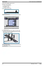
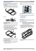
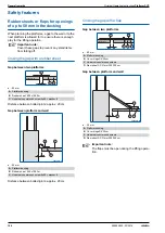
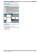
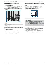
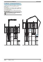
Mount the Ladder suspension SK.

Required nuts & bolts etc.


6 square bolts M10x70


6 washers A 10.5


6 hexagon nuts M 10

(not included with product)

e ... Overlap min. 50

 mm

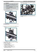
Guide the fixing bolt of the Ladder suspension SK 

through the rung of the ladder and secure on both 

sides with d4 spring cotters.

E

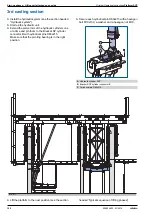
Ladder suspension SK

E

Ladder suspension SK

F

System ladder XS 4.40m

G

Ladder bolt XS

98058-482-01

E

98058-481-02

e

98058-481-03

E

F

G

Summary of Contents for Platform SCP

Page 1: ...ka GmbH A 3300 Amstetten 999805802 03 2016 en GB The Formwork Experts Platform SCP Original Operating Instructions Instructions for assembly and use Method statement by Doka GmbH A 3300 Amstetten 98058 220 01 ...

Page 2: ...2 999805802 03 2016 Original Operating Instructions Platform SCP ...

Page 3: ...Original Operating Instructions Platform SCP 3 999805802 03 2016 ...

Page 4: ...ormwork 35 Plumbing aligning the formwork 38 Start up phases 38 Starting up 40 1st casting section 41 Erecting the working platform and the formwork 46 Attaching the girder grille 50 Suspending the formwork and platforms from the girder grille 54 Mounting the hydraulic cylinders 56 Finishing the platform and enclosure 62 2nd casting section 64 3rd casting section 67 Typical sequence of lifting pha...

Page 5: ...l climbing cones 20 0 138 Start up phases Lifting unit attached on one side 138 Starting up 139 1st casting section 140 Erecting the working platform and the formwork 143 Attaching the girder grille 144 Suspending the formwork and platforms from the girder grille 148 Mounting the hydraulic cylinders 150 Finishing the platform and enclosure 151 2nd casting section 152 3rd casting section 154 Typica...

Page 6: ...y updating a hazard assessment at every job site This booklet serves as the basis for the site specific hazard assessment and for the instructions given to users on how to prepare and utilise the system It does not substitute for these however Remarks on this booklet This booklet can also be used as a generic method statement or incorporated with a site specific method statement Many of the illust...

Page 7: ...ticular anchoring tying components suspension components connector components and castings etc or otherwise subject them to heating Welding causes serious change in the microstruc ture of the materials from which these components are made This leads to a dramatic drop in the failure load representing a very great risk to safety The only articles which are allowed to be welded are those for which t...

Page 8: ...are parts Repairs may only be carried out by the manufacturer or authorised facilities Miscellaneous We reserve the right to make alterations in the interests of technical progress Symbols used The following symbols are used in this booklet Important note Failure to observe this may lead to malfunc tion or damage CAUTION WARNING DANGER Failure to observe this may lead to material damage and to inj...

Page 9: ... MRd Fd Design value of an action Steel Rd Rk Timber Rd kmod Rk Fd F Fk M M F force Fk Characteristic value of an action actual load service load k characteristic e g dead weight live load concrete pressure wind Rk Characteristic value of the resistance e g moment resistance to yield stress F Partial factor for actions in terms of load F force e g for dead weight live load concrete pres sure wind ...

Page 10: ... Stage Operations Scheduling Stage Taking well founded decisions thanks to professional advice and consulting Optimising the preliminary work with Doka as an experienced part ner Controlled regular forming oper ations for greater efficiency resulting from realistically calculated formwork concepts Find precisely the right formwork solutions with the aid of help with the bid invitation in depth ana...

Page 11: ...s are completely transparent there is no need for improvisation dur ing the project and no unpleas ant surprises at the end of it Reduced close out costs Our professional advice on the selection quality and correct use of the equipment helps you avoid damage and minimise wear and tear Concrete Construction Stage Project Close out Stage Optimum resource utilisation with assistance from the Doka For...

Page 12: ...o two opposite walls Lifting unit attached on one side The lifting unit can be attached on one side with the Bracket SCP in the absence of walls if there are openings in the opposite wall Lifting units attached on one side and on both sides are often combined Lifting unit attached on both sides 98058 405 01 Lifting unit attached on one side Lifting unit attached on both sides 98058 406 01 ...

Page 13: ...latforms For more information please contact your Doka techni cian It is forbidden to use the product for anything but its intended purpose Only use serviceable functioning compo nents Do a sight check to see if any parts are damaged Doka accepts no liability for products that have been altered Repairs may only be carried out by the man ufacturer Wherever possible the lifting unit compo nents and ...

Page 14: ...strie GmbH A 3300 Amstetten Austria Designation SCP Project name see rating plate Year of manufacture see rating plate Before every use Check for any signs of damage or visible deforma tion To ensure optimum functioning check the entire Platform SCP while it is in operation to make sure that it stays clean no dried concrete spatter rein forcement steel or timber litter Damaged or deformed parts th...

Page 15: ...y in one lift Integrated platforms stair towers and ladders pro vide complete safety during working operations and for up and down access Rapid working in a systematic sequence Quick and easy to reposition in only a few opera tional steps as it is raised at the push of a button Short forming times as the formwork suspended from the girder grille is easy to close and open Speeds up the workflow as ...

Page 16: ...limbs ahead of the slabs this separation of the structure s components accelerates progress and offers excellent protection against adverse weather conditions Slab and walls cast in one pour In this construction method the floor slabs and walls are cast in one single pour this makes for high cost efficiency and speeds up construction progress still fur ther Core with surrounding slab Core at struc...

Page 17: ...m Erect the vertical scaffold 2nd casting section Erect the girder grille Erect the enclosure and working platform Raise the platform to the next casting section Pour the 2nd section Erect the suspended platforms in the shaft cores where there is a base beam Raise the platform to the next casting section Pour the 3rd section 3rd casting section 98058 432 02 98058 422 15 98058 470 01 98058 416 28 ...

Page 18: ...vious section has been cast All ties have been removed Formwork has been struck Platform is raised Platform travels upwards Lower base beam is pulled up The lifting operation is finished 98058 409 01 98058 409 02 98058 409 03 For detailed information on the lifting sequence see the section headed Typical sequence of lifting phases ...

Page 19: ...orm SCP Lifting unit attached on both sides 19 999805802 03 2016 Platform SCP Lifting unit attached on both sides General overview A Lifting unit B Girder grille C Suspended platform D Facade platform E Railing on girder grille 98058 405 01 A A B E D C ...

Page 20: ...e beam Lower distance profile mm Is fabricated on a project specific basis The lower distance profile is used to adapt the lower base beam to the respective shaft width The plunger rod of the hydraulic cylinder is pinned into the lower distance profile Lower latch beam Is used for transferring the vertical loads in the lifting situation It also has a guiding function for the Vertical pro file FRQ ...

Page 21: ... system Upper cylinder connector SCP Links the hydraulic cylinder to the girder grille Hydraulic cylinder SCP The double acting hydraulic cylinder is used to raise the Platform SCP to the next casting sec tion It is pinned into the lower base beam and the Upper cylinder connector SCP Cylinder head guide SCP This is a bend protector for the Hydraulic cylin der SCP and is attached to the Upper dista...

Page 22: ...latform for placing the reinforcement Storage platform for installing all the infrastructure Attaching all the formwork Attaching all the suspended platforms During the lifting operation the girder grille is lifted along with all the components connected to it A Girder grille B Lifting unit C Formwork D Facade platform 98058 407 01 A B B B B C D The individual components and clamping con nections ...

Page 23: ...or the enclosure Railing on the girder grille The railing on the girder grille is used in the Slab and walls cast in one pour method The Railing profiles IPB140 serve as a supporting con struction for the enclosure A Facade profile HE A180 B WS10 connector F C Multi purpose waling WS10 Top50 D Facade profile connector E Shim F F Enclosure G Girder grille 98058 408 02 B D E G F A C F Enclosure G Gi...

Page 24: ...ofile U300 mm is used to adapt the upper base beam to the respective shaft width Close up of upper base beam g min 2470 mm 4500 mm h length of distance profile shaft width 1630 mm i 800 mm j 60 mm The lower distance profile is used to adapt the lower base beam to the respective shaft width Close up of lower base beam g min 2470 mm 4500 mm h length of distance profile shaft width 1566 mm i 800 mm j...

Page 25: ...ight of casting section Vertical profile 150 Connection point girder grille Connection point lower base beam Connection in longitudinal member position Connection in transverse member position 2 70 2 90 m 450 S355 481 S355 1 1 2 90 3 30 m 481 S355 512 S355 2 1 3 30 3 60 m 512 S355 543 S355 2 2 3 60 3 90 m 543 S355 574 S355 3 2 3 90 4 25 m 574 S355 574 S355 4 3 4 00 4 25 m 574 S355 605 S355 3 2 4 2...

Page 26: ...ng operation i e while the Platform SCP is being moved into a new working position Max permitted loads Upper base beam Lower base beam stationary during lifting a 130 mm b 75 mm c 290 mm d 140 mm a 86 mm b 120 mm c 130 mm V 300 kN V 200 kN H project specific A Support surface for the latches 98058 412 01 V 98058 411 01 V d a c b A A 98058 412 02 H b a 98058 411 02 A c The introduction of the force...

Page 27: ...stem as a whole is determined separately for all the operational phases of each project Working situation Lifting operation Storm winds A max 300kg m2 Level 1 B max 150kg m2 Level 0 1 98058 405 01 B B B B B B A 1 0 1 Max lifting capacity cylinder 400 kN During the lifting operation the sum of the ver tical loads occurring within the range of influ ence of one hydraulic cylinder must not exceed 400...

Page 28: ...f the base beams a 400 mm b 160 mm c 350 mm Shaft width tolerance d width of shaft tolerance 10 mm Right Wrong Right Wrong Important note Position the Latch rolls in such a way that the horizontal loads can be safely transferred Take into account openings in the structure and latch boxes 98058 413 01 98058 413 02 a b 98058 413 03 c 98058 413 05 d A Latch roll 98058 415 03 A 98058 415 04 A 98058 41...

Page 29: ...y protector 22mm D Super plate 15 0 E Tie rod 15 0 length 500 mm F E g plank The positions of the latch boxes must be defined at an early stage when the formwork is being planned and assembled The Doka beams and multi purpose walings of the formwork must not cover the hole drilled for the suspension point 98058 415 01 a 98058 415 02 b 98058 414 01 C A E B D F Inclination of base beam max 0 50 Exam...

Page 30: ... latch remains in the concrete and acts as a support surface for the latches Dismounting the Boxes for latch The work is carried out from the suspended plat form Twist two Tie rods 15 0 into the sockets of the Box for latch until fully engaged The latch boxes are detached from the concrete by means of an auxiliary construction consisting of two Tie rods 15 0 and two Super plates 15 0 A Box for lat...

Page 31: ...Original Operating Instructions Platform SCP Anchoring on the structure 31 999805802 03 2016 ...

Page 32: ...ssible formwork systems Timber beam formwork e g Large area formwork Top 50 Framed formwork e g framed formwork Framax Xlife For more information see the Timber beam formwork Top 50 User Information booklet 98058 400 01 For more information see the Framed form work Framax Xlife User Information booklet 98058 401 01 ...

Page 33: ...ng strap from the suspended formwork Push the suspended formwork outward to the top of the previously cast section Close the formwork and tie it This section only deals with how to operate the formwork For details of how to tie the formwork please see the User Information booklets Large area formwork Top 50 or Framed form work Framax Xlife A Roll back formwork B Holding formwork No persons are all...

Page 34: ...vices props struts or pivot them out of the way Detach the formwork from the concrete After the lifting operation Push back the roll back formwork as far as the stop D Roller safety pin WS10 The Roller safety pins WS10 must be fitted and secured 98058 427 01 D CAUTION Off the wall formwork elements must be fixed on the scaffold e g with a chain or a quick locking strap to secure them against accid...

Page 35: ... with the chain hoist and position it at the right height Tighten the Star grip nut 15 0 Lock the Star grip nut 15 0 with a hexagon nut 15 0 Improper handling and use of the formwork equipment can lead to hazardous situations These must be prevented under all circum stances WARNING It is not allowed to introduce any extra forces into the formwork and scaffold Do not use the formwork to force incor...

Page 36: ...Press the bottom of the formwork against the struc ture edges by extending the Doka floor prop Fasten a spindle strut between the girder grille and formwork Adjust the formwork inclination with the spindle strut A Holding formwork B Doka floor prop type project specific C Spindle strut type project specific 98058 427 04 B C C A A C Spindle strut type project specific D Spindle strut connector SK 9...

Page 37: ... into the sleeve of the Steel waling fixing WS10 until it is fully engaged Swing the tie rod plus Star grip nut 15 0 round and engage it in the holding fixture on the Fixing angle Pin a Double bolt D12 into the Fixing angle and secure it with a Spring cotter d4 Adjust the formwork with the Star grip nut 15 0 A Holding formwork 98058 427 08 A A 98058 427 09 B Steel waling fixing WS10 C Tie rod 15 0...

Page 38: ... Girder grille is supported by 2 Vertical profiles 150 Important note A hard flat firm surface is needed Prepare a sufficiently large assembly area In order to explain the entire lifting sequence as simply as possible the repetitive actions involved are described in detail in separate sec tions of this booklet The sections in question are Mounting the latch boxes see Anchoring on the structure Clo...

Page 39: ...ds 4 Vertical profiles 150 support the girder grille Note Working platforms with two base beams can be assem bled with one or two hydraulic cylinders as necessary Two hydraulic cylinders and two lower base beams are used when the following requirements apply For positioning a concrete placing boom If statically required D Suspension profile FRQ 120 8 m E Girder grille D E 98058 433 03 A Upper base...

Page 40: ... a 800 mm b min 700 mm Undo the form ties Remove the temporary platforms and pouring plat forms Lift the inside formwork out of the shafts In the Slab and walls cast in one pour method a wall plinth and a temporary support for the formwork are needed A Box for latch 15 0 B Wall plinth C Temporary support for formwork D Pouring platform E Temporary platform 98058 435 01 a b A C D E B When used with...

Page 41: ...base beams in the latch boxes Remove the Quick locking strap 55cm from the latches Set down the base beams in the latch boxes Detach the lifting chain from the base beam Put up service towers on the outsides A Lower base beam 98058 430 07 A Latch secured with quick locking strap Latch in latch box B Quick locking strap 55cm C Lower latch The latches of the base beams must be rest ing in the middle...

Page 42: ...s a 10 mm Erecting the vertical scaffold Lift the pre assembled vertical scaffold into the upper base beam Pin each Vertical profile 150 into the base beam with Fastening bolts FRQ150 and secure the bolts with the cotter pins Included with the Vertical profile 150 4 Fastening bolts FRQ 150 8 washers 21 8 cotter pins 5x45 A Platform supports height min 950 mm B Platform with one Upper base beam Lat...

Page 43: ...rm supports in the area of the multi purpose walings Set down the working platform on the supports a 100 mm Positioning the formwork Prepare squared timbers for the correct operational height along the entire length of the formwork Attach the lifting chain to the lifting brackets on the pre assembled formwork Lift in the formwork elements and secure them against tip over H Distribution bolt D50 I ...

Page 44: ...l scaffold gang Lift the pre assembled vertical scaffold gang into the upper base beams Fix the Vertical profiles 150 in the base beam using 4 fastening bolts FRQ 150 for each profile and secure them The following is included with the Vertical profile 150 4 fastening bolts FRQ 150 8 washers 21 8 cotter pins 5x45 B Platform with two upper base beams Latch secured with quick locking strap Latch in l...

Page 45: ...3 distribution bolts D50 3 cotter pins 6 3x90 Positioning the formwork Prepare squared timbers for the correct operational height along the entire length of the formwork Attach the lifting chain to the lifting brackets on the pre assembled formwork Lift in the formwork elements and secure them against tip over H Distribution bolt D50 I Vertical profile FRQ 120 J Squared timber height project speci...

Page 46: ...o files 150 Carefully lower the grille beam unit on to the Vertical profiles 150 Comply with the tolerances specified in the shop drawing assembly plan Take actual measurements and verify them The vertical scaffolds must correspond to the support points on the girder grille If any part of the girder grille does not have enough support points during assembly suf ficiently strong supports must be pr...

Page 47: ...8 hexagon nuts M20 strength grade 8 EN ISO 4032 DIN 934 Girder grille made up of several units Mount the bottom tension plate on the first part of the grille beam unit Bolt the units of the girder grille to each other see the section headed Assembling the girder grille WARNING Do not detach the crane until the girder grille is firmly bolted to the Vertical profiles 150 B Pre assembled girder grill...

Page 48: ...atforms site provided Pass lifting slings around the grille beam pair and attach them to the lifting beam Crane lift the grille beam pair to the vertical profiles Follow the directions in the Lifting beam 110kN 6 00m Operating Instructions A Temporary platform B Pre assembled grille beam pair C Lifting beam 110kN 6 00m 98058 422 11 A A A B C ...

Page 49: ...32 DIN 934 Repeat the procedure to position the other grille beam pairs on the vertical scaffolds Set the grille beam pairs for the transverse members on the Joint plates WU30 Bolt the grille beam pair to the Vertical profiles 150 with threaded rods Pre tension the Clamping connections WU30 see the section headed Clamping connections for assembling the girder grille Ensure that the Clamping plate ...

Page 50: ...ll using roll back formwork enough space is created for working between off the wall formwork elements Off the wall formwork elements must be fixed on the scaffold e g with a chain or a quick locking strap to secure them against accidental motion dislocation or swinging A Roll back formwork B Holding formwork 98058 422 01 A A A A B B B B Close up A Roller unit SK roll back formwork Close up B Elem...

Page 51: ...older 1 Raise the locking plate 2 Screw the tie rod into the Tie rod holder 15 0 until it protrudes by approx 20 mm 3 Push the locking plate onto the tie rod This fixes the tie rod so that it cannot be turned c approx 20 mm Important note The excess length of the tie rod below the star grip nut must be at least as large as the clearance between the formwork and the working platform A Roller unit S...

Page 52: ...nit FRQ 50 B and secure it Fix the Multi purpose waling WS10 Top50 of the working platform to the Suspension profile FRQ 50 and secure it A Platform support height min 950 mm B Platform with one upper base beam C Suspension profile FRQ 50 98058 422 10 B A A 98058 416 12 C C Suspension profile FRQ 50 project specific D Clamping unit FRQ 50 B E Connecting pin 10cm F Spring cotter 5mm C Suspension pr...

Page 53: ...readed rods Threaded fastener material required for each Suspen sion profile FRQ 120 8 4 threaded rods M20 length 400 mm strength grade 8 8 8 washers 20 EN ISO 7089 8 hexagon nuts M20 strength grade 8 EN ISO 4032 DIN 934 Raise the platform with the chain hoist and bolt it to the Suspension profile FRQ120 8 Threaded fastener material required for each Suspen sion profile FRQ 120 8 2 hexagon bolts M...

Page 54: ... Upper cyl inder connector SCP Lift the pre mounted hydraulic cylinder into the shaft see final drawing or assembly drawing Important note Note the installation position of the Upper cylin der connector SCP and the position of the clamping angles M7 A Hydraulic cylinder SCP B Upper cylinder connector SCP C Clamping angle M7 98058 421 01 B A C 98058 416 08 ...

Page 55: ...65 10 9 in every case Use new screw sets every time the equip ment is re assembled The bolted joints must comply with EN 1090 2 C Clamping angle M7 D Grille beam pair U300 98058 421 02 C D 98058 421 05 Important note The Cylinder head guide SCP has to be mounted on the topside or the underside of the base beam depending on the height of the casting section Cylinder head guide SCP mounted on topsid...

Page 56: ...working platform and guide it towards the girder grille with the aid of tag lines Bolt Doka beams H20 on to the girder grille profile U300 with Beam clamps U300 double Fix the Beam clamps U300 double in the Doka beams H20 with universal countersunk screws 5x50 Detach the crane suspension tackle from the work ing platform 98058 416 10 A Grille beam U300 B Doka beam H20 C Beam clamp U300 double D Un...

Page 57: ...profile IPB140 with the aid of tag lines Clamp pre assembled enclosure elements to the Railing profiles IPB 140 Detach the crane suspension tackle from the enclo sure element Remove the Enclosure SCP lifting rings E Enclosure SCP lifting ring F Enclosure element Follow the directions in the Enclosure SCP lift ing ring Operating Instructions F Enclosure element G Railing profile IPB140 92865 201 03...

Page 58: ...lti purpose waling WS10 Top50 and fix them with Beam screws S 8 70 see final drawing or assembly drawing Fasten platform decking to the Doka beams with suf ficient numbers of universal countersunk screws 6x80 A Grille beam pair U300 B Facade profile connector C Facade profile HE A180 98058 416 05 A B C WARNING Risk of fracture if unsuitable bolts are used Use only the Screw set SCP M24x75 10 9 in ...

Page 59: ... profiles above the platform decking Detach the crane suspension tackle from the enclo sure element Remove the Enclosure SCP lifting rings Clamp further enclosure elements to the facade pro files in the same way Note The top enclosure element is not mounted until later H Enclosure SCP lifting ring I Enclosure element Follow the directions in the Enclosure SCP lift ing ring Operating Instructions B...

Page 60: ...latform Crane lift the pre assembled working platform and guide it towards the girder grille with the aid of tag lines Clamp pre assembled enclosure elements above the platform decking to the facade profiles HE A180 Final mounting of ladders manholes and other safety devices see the section headed Ladder sys tem 98058 416 03 ...

Page 61: ...Original Operating Instructions Platform SCP Start up phases 61 999805802 03 2016 ...

Page 62: ...ing bearing is in the right position Secure each cylinder bolt D80x215 with a hexagon bolt M10x100 a washer and a hexagon nut M10 Lift the platform to the next position see the section headed Typical sequence of lifting phases Lower base beam is pulled up Remove the service towers from the outsides Apply concrete release agent and set up one side of the formwork Adjust the formwork Mount the Boxes...

Page 63: ...Original Operating Instructions Platform SCP Start up phases 63 999805802 03 2016 Pour the 2nd section Strike the formwork Clean the formwork 98058 416 01 ...

Page 64: ...ngth grade 8 8 EN ISO 4017 DIN 933 2 washers 20 EN ISO 7089 2 hexagon nuts M20 strength grade 8 EN ISO 4032 DIN 934 Pin the Multi purpose waling WS10 Top50 to the Suspension profiles FRQ 50 and secure with spring cotters Use beam screws to fix Doka beams onto the Multi purpose waling WS10 Top50 and the U100 profile Fasten platform decking to the Doka beams with suf ficient numbers of universal cou...

Page 65: ...y devices see the section headed Ladder sys tem Close off all openings in the decking on the main working platform and on the suspended platform Pin distribution bolts to the Vertical profiles FRQ 120 as lifting stops and secure with spring cotters a casting section height 150 mm Apply concrete release agent and set up one side of the formwork Adjust the formwork Mount the Boxes for latch Place th...

Page 66: ...66 999805802 03 2016 Start up phases Original Operating Instructions Platform SCP Pour the 3rd section Open the formwork Clean the formwork 98058 405 01 ...

Page 67: ...lifting phases Lifting unit attached on one side Important note Before lifting Remove any loose items from the formwork and platforms or secure them firmly CAUTION Max wind speed for climbing operations 72 km h Heed all storm warnings and take action as necessary Only begin climbing operations that you can be sure of finishing before wind speeds rise too high While the platform is being raised the...

Page 68: ... base beam have been swivelled into the same recess in the concrete but are not resting on it The previous section has been cast All ties have been removed The travel path is free of obstacles The formwork has been rolled back as shown in the shop drawing assembly plan by approx 10 cm Suspended off the wall formwork elements have been fixed to the scaffold to secure them against accidental motion ...

Page 69: ...tton for as long as nec essary until the latches of the lower base beam have automatically swivelled into the latch boxes of the new casting section Switch off the hydraulic unit The lifting operation is finished Important note Do not move the lower base beam down into the recess in the concrete The latches of the lower base beam remain unloaded 98058 409 03 ...

Page 70: ...e possible Depending on the project the actual design may thus differ very greatly from the basic type described here In these cases you should discuss the assembly procedure with your Doka technician Follow the shop drawing assembly plan Important note A hard flat firm surface is needed Prepare a sufficiently large assembly area All platforms must be statically verified ...

Page 71: ...ARNING Risk of fracture if unsuitable screws are used Use only the Screw set M24x85 10 9 in every case Use NEW Screw sets every time the equip ment is re assembled The threaded joints must comply with EN 1090 2 A Lower distance profile mm project specific B Lower latch beam B Lower latch beam C Lower latch 98058 436 03 A B 98058 436 04 B C a 98058 436 01 When the base beam is being lifted into the...

Page 72: ...ure with spring cotters Set dimension a to 49 mm factory setting Set dimension b to 47 mm factory setting a 49 mm b 47 mm Preparations for lifting in WARNING Risk of fracture if unsuitable bolts are used Use only the Screw set SCP M24x75 10 9 in every case Use new screw sets every time the equip ment is re assembled The bolted joints must comply with EN 1090 2 D Tension plate U300 E Tension plate ...

Page 73: ...9 A Hardwood blocking B Vertical profile 150 S355 C Bracing shoe double D Bracing shoe triple WARNING Risk of fracture if unsuitable bolts are used Use only the Screw set M24x65 10 9 in every case Use new screw sets every time the equip ment is re assembled The bolted joints must comply with EN 1090 2 C Bracing shoe double D Bracing shoe triple 98058 438 01 A B B C D 98058 438 03 C 98058 438 04 D ...

Page 74: ...sembly plan Required nuts bolts etc 2 hexagon screws M16x40 strength grade 8 8 EN ISO 4017 DIN 933 2 washers 16 EN ISO 7089 2 hexagon nuts M16 strength grade 8 EN ISO 4032 DIN 934 A Plumbing strut 260 IB B Doka express anchor 16x125mm WARNING Risk of fracture if unsuitable bolts are used Use only the Screw set M24x65 10 9 in every case Use new screw sets every time the equip ment is re assembled T...

Page 75: ... plan Take actual measurements and verify them The vertical scaffolds must correspond to the support points on the girder grille WARNING Risk of fracture if unsuitable bolts are used Use only the Screw set SCP M24x75 10 9 in every case Use new screw sets every time the equip ment is re assembled The bolted joints must comply with EN 1090 2 Important note A gap at the join between beams can result ...

Page 76: ...ition joint plates on the grille beams Bolt the joint plates and clamping plates on with threaded rods a 370 mm Threaded fastener material required 4 threaded rods M20 length 750 mm strength grade 8 8 8 washers 20 EN ISO 7089 8 hexagon nuts M20 strength grade 8 EN ISO 4032 DIN 934 A Grille beam U300 B Squared timber length 500 mm C Super plate 15 0 D Tie rod 15 0 length 1000 mm E Doka beam H20 len...

Page 77: ... Assembling the transverse members Set down Grille beams U300 on the joint plates Mount facade profile connector or railing profile at the edge area of a grille beam unit Important note Guide value for one grille beam unit Area approx 100 m2 Consider what craneage is available Note the weights stated in the final drawing or assembly drawing A Grille beam U300 B Joint plate WU30 C Joint plate WU30F...

Page 78: ...78 999805802 03 2016 Pre assembly Original Operating Instructions Platform SCP Finish the clamping joints Mount formwork suspension devices on the girder grille 98058 444 05 ...

Page 79: ...eaded fastener material required 2 Screw sets SCP M24x75 10 9 The washers supplied with the screw set are not required for bolting the railing profiles A Grille beam U300 B Facade profile connector C Clamping unit WU30 F single D Clamping unit WU30 F double 98058 441 02 A B 98058 444 10 C C D WARNING Risk of fracture if unsuitable bolts are used Use only the Screw set SCP M24x75 10 9 in every case...

Page 80: ...the clamping connection by hand Position the hollow piston cylinder with the pressure support over a threaded rod Mount the Tensioning tool M20 on the threaded rod a 25 35 mm Apply a pre loading force of 100 kN by operating the hand pump Re tighten the hexagon nuts and release the load from the hollow piston cylinder Pre load all the other threaded rods of the clamping connection WU30 in the same ...

Page 81: ...grade 8 8 4 washers 20 EN ISO 7089 4 hexagon nuts M20 strength grade 8 EN ISO 4032 DIN 934 Clamping connection WU30 F double Used at intersection point of grille beam pairs U300 with a Facade profile connector in the longitudinal and transverse members Threaded fastener material required 1 threaded rod M20 length 800 mm strength grade 8 8 2 washers 20 EN ISO 7089 2 hexagon nuts M20 strength grade ...

Page 82: ... 4 hexagon nuts M16 strength grade 8 EN ISO 4032 DIN 934 Suspending platforms on Suspension profiles FRQ 120 8 m Secure the Suspension profile FRQ 120 8 to the girder grille with threaded rods Threaded fastener material required 4 threaded rods M20 length 400 mm strength grade 8 8 8 washers 20 EN ISO 7089 8 hexagon nuts M20 strength grade 8 EN ISO 4032 DIN 934 A Grille beam U300 B Head fixing plat...

Page 83: ... The following is included with the Roller unit U300 1 hexagon screw M16x70 1 washer 16 1 hexagon nut M16 Mounting the Element suspender SK Clamp the Element suspender to the Grille beam U300 Threaded fastener material required 2 threaded rods M16 length 400 mm strength grade 8 8 4 washers 16 EN ISO 7089 4 hexagon nuts M16 strength grade 8 EN ISO 4032 DIN 934 Pin a Tie rod holder 15 0 onto the Ele...

Page 84: ...rille beams U300 Threaded fastener material required 2 threaded rods M16 length 450 mm strength grade 8 8 4 washers 16 EN ISO 7089 4 hexagon nuts M16 strength grade 8 EN ISO 4032 DIN 934 Clamping connection between 2 Multi purpose walings WS10 Top50 Threaded fastener material required for each connec tion 1 threaded rod M16x250 1 washer 16 1 hexagon nut M16 A Grille beam U300 B Multi purpose walin...

Page 85: ...the pins Threaded fastener material required for each Element suspender SK 1 hexagon bolt M20x100 1 washer 16 1 hexagon nut M16 at the intersection point of 2 Multi purpose walings WS10 Top50 Clamp the Element suspender into position at the intersection of 2 Multi purpose walings WS10 Top50 Pin a Tie rod holder 15 0 onto the Element suspen sion and secure the pins Threaded fastener material requir...

Page 86: ...ng angles as shown in the final drawing or assembly drawing Threaded fastener material required 3 Screw sets M24x65 10 9 Note The cylinder connector is installed with the closed end up or down depending on store height see the section headed System dimensions A Hydraulic cylinder SCP B Upper cylinder connector SCP WARNING Risk of fracture if unsuitable bolts are used Use only the Screw set M24x65 ...

Page 87: ...nds of the Custom profiles U200 Threaded fastener material required for each latch roll 4 hexagon bolts M20x60 strength grade 8 8 EN ISO 4017 DIN 933 4 washers 20 EN ISO 7089 4 hexagon nuts M20 strength grade 8 EN ISO 4032 DIN 934 Adjust the Latch roll for dimension a see final draw ing or assembly drawing Note To fasten the Doka beams H20 onto the base beams a longer hexagon bolt is needed for th...

Page 88: ... 2 x 200 mm Manhole Cut out the opening for the manhole c 710 mm d 610 mm Screw the Manhole B 70 60cm onto the platform decking with universal countersunk screws 5x40 G Platform decking Raw sheet 3 S 38mm H Opening in decking for latch 490x180 mm I Opening in decking for vertical scaffold 240x300 mm J Opening in decking for hydraulic cylinder 320x320 mm 98058 443 01 G 98058 443 02 a b H I J K Manh...

Page 89: ... c 250 mm d 350 mm Mount Platform roller units on the platform decking e 50 mm Threaded fastener material required 2 square bolts M10x60 2 washers A10 5 2 hexagon nuts M10 self locking A Upper base beam U300 B Multi purpose waling WS10 Top50 C Doka beam H20 D Beam screw S8 70 E Beam screw S8 70 longer hexagon bolt necessary 98058 445 04 A B C E D x y a 98058 445 03 F Platform decking Raw sheet 3 S...

Page 90: ...tform with Platform cross double Pin the Multi purpose walings WS10 Top50 to the platform cross and secure the pins Lay down the platform crosses with Multi purpose walings WS10 Top50 spaced apart by the exact centre to centre distance Mount Doka beams H20 to the multi purpose wal ings Width across 13 mm Hole diameter 10 mm L Manhole B 70 60cm 98058 445 07 f g 98058 445 06 L A Multi purpose waling...

Page 91: ...oss 13 mm Hole diameter 10 mm Fasten platform decking to the Doka beams with suf ficient numbers of universal countersunk screws 6x80 Cut out needed in platform decking a 250 mm b 350 mm Mount Platform roller units on the platform decking see the section headed Working platform with one base beam G Platform decking Raw sheet 3 S 38mm H Opening in decking for Suspension profile FRQ 120 8 150x150 mm...

Page 92: ...tersunk screws 6x80 Cut out needed in platform decking a 250 mm b 350 mm Mount Platform roller units on the platform decking see the section headed Working platform with one base beam Manhole Cut out the opening for the manhole c 710 mm d 610 mm Screw the Manhole B 70 60cm onto the platform decking with universal countersunk screws 5x40 A Multi purpose waling WS10 Top50 B Doka beam H20 B Doka beam...

Page 93: ...form decking to the Doka beams with suf ficient numbers of universal countersunk screws 6x80 Manhole Cut out the opening for the manhole a 710 mm b 610 mm Screw the Manhole B 70 60cm onto the platform decking with universal countersunk screws 5x40 A Doka beam H20 B Platform decking Raw sheet 3 S 38mm 98058 450 01 A B C Manhole B 70 60cm 98058 450 03 b a 98058 450 02 C ...

Page 94: ... 6x90 Fix Enclosure clamps SCP onto the webs of the H20 beams using hexagon bolts Width across 30 mm Hole diameter 22 mm Included in scope of supply 2 hexagon bolts M20x90 2 washers 20 EN ISO 7089 2 hexagon nuts M20 strength grade 8 EN ISO 4032 DIN 934 A Doka beam H20 B Plank 5x20 cm C Enclosure clamp SCP Important note If a 2 0 m or b 4 0 m then an extra stiffen ing reinforcement must be added in...

Page 95: ...sheeting Align the trapezoidal sheets on the frame and screw them down Mount further trapezoidal sheets with an overlap B Plank 5x20 cm C Enclosure clamp SCP B Plank 5x20 cm 98058 452 03 C B 98058 452 06 a c b B C Enclosure clamp SCP D Enclosure SCP lifting ring Follow the directions in the Enclosure SCP lift ing ring Operating Instructions Important note Before installing the trapezoidal sheeting...

Page 96: ...P onto the Facade pro file Required nuts bolts etc 2 hexagon screws M16x50 strength grade 8 8 EN ISO 4017 DIN 933 2 washers 16 EN ISO 7089 2 hexagon nuts M16 strength grade 8 EN ISO 4032 DIN 934 WARNING Risk of fracture if unsuitable bolts are used Use only the Screw set M24x65 10 9 in every case Use new screw sets every time the equip ment is re assembled The bolted joints must comply with EN 109...

Page 97: ...irm surface is needed Provide a sufficiently large dismantling space Important note Before lifting Remove any loose items from the formwork and platforms or secure them firmly Passenger transportation is forbidden Exposed fall hazard locations must be closed off by attaching side railings During all assembly and dismantling work on the Platform SCP that is carried out on the structure itself the o...

Page 98: ...smount the Cylinder head guide SCP Dismount the threaded rods M24 Dismount the bottom clamping angles Attach the lifting chain to the Upper cylinder connec tor SCP Important note If the plunger rod is contaminated e g with concrete laitance Carefully clean the plunger rod before retracting the cylinders Do not hit any objects against the plunger rod A Hydraulic cylinder SCP B Lower base beam C Cyl...

Page 99: ...e Enclo sure clamp SCP of the enclosure element as far as it will go Attach the lifting chain to the lifting rings of the enclo sure element Undo the enclosure clamps of the enclosure element that has been attached to the crane Lift the enclosure element off the platform and set it down 98058 416 22 Follow the directions in the Enclosure SCP lift ing ring Operating Instructions A Enclosure SCP lif...

Page 100: ...rom the girder grille and set it down Attach the lifting chain to the lifting brackets on the formwork gang Dismount the element suspender or roller unit from the waling Lift the formwork element off the platform and set it down CAUTION Off the wall formwork elements must be fixed on the scaffold e g with a chain or a quick locking strap to secure them against accidental motion dislocation or swin...

Page 101: ...eam Secure platforms with one base beam to the vertical scaffold with lashing straps Dismount the suspension profiles between the girder grille and the working platforms Important note Secure the vertical scaffold to the structure so that it cannot tip over Take into account the loads imposed by the formwork A Platform with one upper base beam B Lashing strap 5 00m 98058 467 02 A B B ...

Page 102: ...ific bracket recess for Doka beams H20 recess for latches Dismount the suspension profiles between the girder grille and the supported platforms CAUTION The supports for the platforms must be checked by the structural designer The formwork is set down on these platforms later in the disassembly procedure The tie holes in the concrete can be helpful for supporting the platforms Important note Take ...

Page 103: ...ing platform with panel struts Fix each panel strut to the working platform with a tie rod and super plates Loosen the star grip nut to lower the formwork onto the working platform Dismount the tie rods from which the formwork was suspended B Panel strut C Tie rod 15 0mm D Super plate 15 0 B D C 98058 416 30 E Star grip nut 15 0 G F Hexagon nut 15 0 98071 270 03 E F G Squared timber height project...

Page 104: ...he area of the Vertical profiles 150 Crane lift the girder grille clear and carefully set it down Important note If any part of the girder grille does not have enough support points during disassembly suf ficiently strong supports must be provided at site The loads imposed on individual supports are shown in the project plans WARNING Do not cut through pretensioned connec tions cutting torch angle...

Page 105: ...ating Instructions Platform SCP Dismantling 105 999805802 03 2016 All other dismantling steps are carried out on the ground in the opposite order of steps from those in which the equipment was assembled 98058 467 01 ...

Page 106: ... lift the formwork element off the working platform Set down and dismantle the formwork element Dismounting the lifting units and suspended platforms Working platform with two base beams Fix the lower base beam to the Vertical profile FRQ 120 6 00m and secure it Dismount the ladder Attach the lifting chain to the vertical scaffold Lift the vertical scaffold and the platforms connected to it out of...

Page 107: ...e beam in the same way as the working platform with two base beams Working platform with no base beams suspended platform Attach the lifting chain to the suspended platform Lift the suspended platform out of the shaft and set it down on the ground Dismount the latch boxes and supports working from a suitable crane cage 98058 468 03 98058 468 05 98058 468 04 ...

Page 108: ...own in document with 4 way U300 join above verti cal profile a min 2470 mm b 700 mm Design variant with only one tier of U300 grille beams above the vertical profile a min 2320 mm b 700 mm A Vertical profile B Hydraulic cylinder SCP C Latches D Distance profile E Latch beam F Special base beam G Grille beam U300 longitudinal and transverse members 98058 466 01 a b b A B C D E 98058 466 02 A G 9805...

Page 109: ... with only one tier of U300 grille beams above the vertical profile Latch beam is integrated in Dis tance profile a min 1880 mm b 510 mm Design variant Vertical scaffold is rotated 90 Latch beam is integrated in Dis tance profile a min 1400 mm A Vertical profile B Hydraulic cylinder SCP C Latches D Distance profile E Latch beam F Special base beam G Grille beam U300 longitudinal and transverse mem...

Page 110: ... the various different types of base beam shown schematically Design variant for wide base beam spans a 4500 mm b 700 mm A Vertical profile B Hydraulic cylinder SCP C Latches D Distance profile E Latch beam F Special base beam G Grille beam U300 longitudinal and transverse members 98058 466 08 a b b A B C E F ...

Page 111: ...ua tions Lower base beam Support SCP Is anchored to the structure for transferring loads Support SCP lower distance profile mm Is fabricated on a project specific basis The lower distance profile is used to adapt the lower base beam to the respective shaft width Is used for transferring the vertical loads in the lifting situation The plunger rod of the hydraulic cylinder is pinned into the lower d...

Page 112: ...ith 4 Universal climbing cones 20 0 Note See the section headed Anchoring on the structure Lifting unit attached on one side 98058 464 02 a c a g e d f b i h j k 98058 465 02 A Climbing cone SCP 20 0 B Sealing sleeve SCP 20 0 C Stop anchor 20 0 expendable anchoring component D Depth mark E Cone screw M36 SW50 9cm F Support SCP G Washers 36 DIN EN 14399 6 A Universal climbing cone 20 0 B Sealing sl...

Page 113: ...ofile with 2 chains Erecting the main working platforms Set down the working platform centred on the Sup ports SCP Use a hexagon bolt to connect the distance profile and the support Additionally secure each Support SCP to the dis tance profile with 2 chains Adjust the latch rolls F Support SCP G Lower distance profile support SCP mm project specific F Support SCP G Lower distance profile support S...

Page 114: ...114 999805802 03 2016 Design variants Original Operating Instructions Platform SCP ...

Page 115: ... no effect on the basic struc ture of the girder grille suspended platform facade platform and railing profile The description in this section refers only to the lifting unit attached at one side The lifting unit can be attached on one side with the Bracket SCP in the absence of walls if there are openings in the opposite wall A Lifting unit attached on both sides B Lifting unit attached on one si...

Page 116: ...S355 Is fixed in the upper brackets and connects the upper brackets to the girder grille Bracing Is fabricated on a project specific basis For transferring horizontal loads Suspended platforms For detaching and fixing the suspension shoes during the lifting operation Consisting of Suspension profile FRQ 50 Is fabricated on a project specific basis Is used for linking the different platform levels ...

Page 117: ...ing position The previous section has been cast All ties have been removed Formwork opened Platform is raised Platform travels upwards Lower bracket is brought up The lifting operation is finished 98058 406 03 98058 406 04 98058 406 05 For detailed information on the lifting sequence see the section headed Typical sequence of lifting phases ...

Page 118: ...riginal Operating Instructions Platform SCP System dimensions a 700 mm b 2000 mm c 100 mm d Height of casting section 2700 mm 4250 mm e approx 1000 mm f 500 mm g min 350 mm g min 350 mm h 400 mm g min 600 mm a e c d 98058 406 06 b 98058 406 07 g f 98058 406 08 g h h h i i ...

Page 119: ...n Vertical profile 150 Connection point girder grille Connection in longitudinal member position Connection in transverse member position 2 70 2 90 m 450 S355 481 S355 1 2 90 3 30 m 481 S355 512 S355 2 3 30 3 60 m 512 S355 543 S355 2 3 60 3 90 m 543 S355 574 S355 3 3 90 4 25 m 574 S355 574 S355 4 4 00 4 25 m 574 S355 605 S355 3 4 25 4 50 m 605 S355 636 S355 3 Connection point girder grille 1 2 3 4...

Page 120: ...nchored state i e while construction tasks are being carried out Loads occurring during the lifting operation i e while the Platform SCP is being moved into a new working position Max permitted loads Two Brackets SCP top One Bracket SCP bottom static during lifting 2 x V1 300 kN 600 kN V2 400 kN 98058 459 01 V1 V1 98058 459 02 V2 The introduction of the forces the transfer of these forces into the...

Page 121: ...live load of the system as a whole is determined separately for all the operational phases of each project Working situation Lifting operation Storm winds A max 300kg m2 level 1 B max 150kg m2 levels 0 1 2 98058 406 01 A B B B B B B 1 2 1 0 Max lifting force per cylinder 400 kN During lifting it is not permissible for the sum of the vertical loads in the area of influence of any one hydraulic cyli...

Page 122: ...d later avoid mixing different types of stop anchor to exclude the risk of confusion on the jobsite a Tie rod length 17 5 cm b Installation depth 31 5 cm c Minimum wall thickness 33 5 cm where the concrete cover is 2 cm c Minimum wall thickness 34 5 cm where the concrete cover is 3 cm d Concrete cover e Size of stop anchor plate 90 mm Important note Use only the Tie rod system 20 0 with Doka autom...

Page 123: ...tted opposite one another and joined with a tie rod Unscrewing the anchoring component on one side may cause the anchoring point on the opposite side to shear off Every suspension point must have its own separate anchorage Exception Suspension points prepared with a Stop anchor double ended 20 0 98058 455 02 b c a 98058 455 03 A Climbing cone SCP 20 0 B Sealing sleeve SCP 20 0 expendable anchoring...

Page 124: ...nsion point resulting in injury and damage Use only the Cone screw M36 SW50 9cm for the positioning point and suspension point head of screw is yellow It is forbidden to use the Positioning disk M36 to prepare a positioning point WARNING Sensitive rod steel Never weld or heat tie rods Tie rods that are damaged or have been weakened by corrosion or wear must be withdrawn from use The axis of the Cl...

Page 125: ...ers of repeat uses Possible thicknesses of form ply 18 27 mm In order to fit the form ply protector a 48 mm diam hole must be drilled in the form ply first Where necessary the Form ply protector 38mm can be closed off with a Framax Xlife plus frame hole plug 38mm included with product If the positioning point is located close to a Doka beam the Climbing cone SCP can be fixed with the Positioning s...

Page 126: ...t place concrete from directly above the stop anchors These measures prevent the anchors from working loose during pouring and vibration A Climbing cone SCP 20 0 B Sealing sleeve SCP 20 0 expendable anchoring component C Stop anchor 20 0 17 5cm 90 expendable anchoring component D Depth mark K Socket connector M36 of the Positioning clamp M36 L M10 wing bolt of the Positioning clamp M36 Nail the M1...

Page 127: ...cured with 2 Cone screws M36 SW50 9cm The Bracket SCP suspension shoe must be flush against the concrete Reversible ratchet 3 4 Reversible ratchet 3 4 with extension The required cube compressive strength of the con crete at the time of loading must be specified sepa rately for each project by the structural designer It will depend on the following factors load actually occurring length of the sto...

Page 128: ...and dowel so that it cannot be unscrewed The required cube compressive strength of the con crete and ready mix mortar at the time of loading must be specified separately for each project by the struc tural designer It will depend on the following factors load actually occurring wall thickness reinforcement extra reinforcement steel distance from edge The introduction of the forces the transfer of ...

Page 129: ...00 SD adhesive or an equivalent product Glue in a tie rod with Climbing cone SCP 20 0 b 215 mm c diam 95 mm Comply with the manufacturer s installation instructions for the adhesive A Climbing cone SCP 20 0 B Sealing sleeve SCP 20 0 expendable anchoring component C Tie rod 20 0mm expendable anchoring component D Adhesive Hilti HIT RE 500 SD or equivalent product E Cone screw M36 SW50 9cm Important...

Page 130: ...hored to the structure and is used for load transfer The suspension shoe is not rigidly connected to the Bracket SCP This facilitates the jobs of installation on and removal from the structure Important note Use only the Tie rod system 20 0 with Doka automatic climbing formwork Risk of confusion If Doka automatic climbing formwork is being used jointly with other Doka climbing sys tems then the Ti...

Page 131: ... 19 cm where the concrete cover is 2 cm c Minimum wall thickness 20 cm where the concrete cover is 3 cm d Concrete cover e Size of stop anchor plate 90 mm WARNING The short Stop anchor 20 0 11 5cm 90 has a much lower load bearing capacity than the Stop anchor 20 0 17 5cm 55 For this reason the short stop anchor is only allowed to be used on systems with low ten sile loads at the anchoring location...

Page 132: ...site one another and joined with a tie rod Unscrewing the anchoring component on one side may cause the anchoring point on the opposite side to shear off Every suspension point must have its own separate anchorage Exception Suspension points prepared with a Stop anchor double ended 20 0 a 98037 281 01 b c 98037 281 02 A Universal climbing cone 20 0 B Sealing sleeve K 20 0 expendable anchoring comp...

Page 133: ...d of screw is red WARNING Sensitive rod steel Never weld or heat tie rods Tie rods that are damaged or have been weakened by corrosion or wear must be withdrawn from use The axis of the universal climbing cone must be at right angles to the surface of the con crete maximum angle of deviation 2 The universal climbing cone must be embed ded so that it is flush with the concrete sur face Tolerance fo...

Page 134: ...the depth mark Push the Cone screw B 7cm through the form facing screw it into the Universal climbing cone and tighten it firmly Tools needed Centre drill bit diam 46 mm Reversible ratchet 3 4 Spanner for Universal climbing cone 15 0 20 0 Extension 20cm 3 4 Box nut 50 3 4 for Cone screw B 7cm Important note Secure the Positioning template SCP to the form ply to ensure that the holes are accu ratel...

Page 135: ...pletely pushed onto the Universal climbing cone The depth mark on the stop anchor must be right up against the universal climbing cone must be screwed in to the full depth The two positioning points of a Suspension shoe must be mounted at the same height with max 2 deviation from the horizontal Mark the top edge of the formwork to make the positions of the stop anchors easier to find when the conc...

Page 136: ... dowel so that it cannot be unscrewed The required cube compressive strength of the con crete and ready mix mortar at the time of loading must be specified separately for each project by the struc tural designer It will depend on the following factors load actually occurring wall thickness reinforcement extra reinforcement steel distance from edge The introduction of the forces the transfer of the...

Page 137: ...nce from edge d centre to centre spacing of anchors e wall thickness Zd design value of the tensile load on the anchor group F 1 5 Vd design value of the shear force on the anchor group F 1 5 Example Basic data Vk vertical load 400 kN Zk tensile load 150 kN F Safety factor 1 5 Zd Zd 150 Zk x 1 5 F 225 kN Vd Zd 400 Zk x 1 5 F 600 kN Note Actual loads have to be ascertained on a project spe cific ba...

Page 138: ...r to explain the entire lifting sequence as simply as possible the repetitive actions involved are described in detail in separate sec tions of this booklet The sections in question are Preparing the positioning points and suspen sion points see Anchoring on the struc ture Closing the formwork see Closing the form work Striking see Opening the formwork For instructions on tying and joining the for...

Page 139: ...of the formwork Place the reinforcement Mount the positioning points Set up the opposing formwork and place the ties Pour the 1st section a height of casting section 2700 mm 4250 mm b min 500 mm c min 350 mm Open the formwork Clean the formwork Set the gang form down on a flat surface with the form ply facing downwards Prepare the formwork for the climbing operation 98058 461 03 b c a ...

Page 140: ...embling the upper brackets Bolt the Bracket SCP strut connection to the upper Bracket SCP Securing brackets to the structure Position the suspended platforms in the shaft Install the Bracket SCP suspension shoes for the next casting section Remove the fixing plate from the Bracket SCP sus pension shoe Width across 30 mm A Bracket SCP B Bracket SCP cylinder connector B C Support roller in parking p...

Page 141: ...e suspension tackle to the working platform Crane lift the pre assembled working platform and guide it towards the upper brackets with the aid of tag lines Pin the working platform to the Brackets SCP and and secure the pins with Spring cotters 5mm A Bracket SCP E Bracket SCP suspension shoe A Bracket SCP E Bracket SCP suspension shoe F Fixing plate The Suspension shoes SCP are crane lifted togeth...

Page 142: ...re squared timbers for the correct operational height along the entire length of the formwork Attach the crane suspension tackle to the lifting brackets on the pre assembled formwork Lift in the formwork elements and secure them against tip over Mount temporary platforms site provided Important note Overload of the temporary reshore Dimension the reshoring of the working plat form adequately The f...

Page 143: ...02 03 2016 Attaching the girder grille Mount the girder grille on the vertical scaffolds see the Lifting units attached on both sides version in section headed Assembling the girder grille Install the diagonal strut between bracket and girder grille as per the final drawing or assembly drawing 98058 461 01 ...

Page 144: ... girder grille Fix the Suspension profile FRQ 50 to the Clamping unit FRQ 50 B and secure it Fix the Multi purpose waling WS10 Top50 of the working platform to the Suspension profile FRQ 50 and secure it Remove the floor props A Working platform B Suspended platform 98058 458 04 A B C Suspension profile FRQ 50 project specific D Clamping unit FRQ 50 B 98058 424 02 E F D C E Connecting pin 10cm F S...

Page 145: ...Top50 of the suspended platform to the Suspension profiles FRQ 50 and secure the pins with spring cotters Important note Do not secure the platforms to the lower brackets C Suspension profile FRQ 50 project specific E Connecting pin 10cm F Spring cotter 5mm G Multi purpose waling WS10 Top50 98058 405 10 F G E C C Suspension profile FRQ 50 project specific E Connecting pin 10cm F Spring cotter 5mm ...

Page 146: ...n the opened formwork panels with the formwork on one side as roll back formwork Off the wall formwork elements must be fixed on the scaffold e g with a chain or a quick locking strap to secure them against accidental motion dislocation or swinging A Roll back formwork B Holding formwork 98058 458 05 A A A B B B Close up A Roller unit SK roll back formwork Close up B With element suspender holding...

Page 147: ...d in the tie rod holder 1 Raise the locking plate 2 Screw the tie rod into the Tie rod holder 15 0 until it protrudes by approx 20 mm 3 Push the locking plate onto the tie rod This fixes the tie rod so that it cannot be turned c approx 20 mm Important note The excess length of the tie rod below the star grip nut must be at least as large as the clearance between the formwork and the working platfo...

Page 148: ...sion tackle to the Upper cyl inder connector SCP Lift the pre mounted hydraulic cylinder into the shaft see final drawing or assembly drawing Important note Note the installation position of the Upper cylin der connector SCP and the position of the clamping angle M7 A Hydraulic cylinder SCP B Upper cylinder connector SCP C Clamping angle M7 98058 421 01 B A C 98058 458 02 ...

Page 149: ... 10 9 4 threaded rods M24 length 450 mm strength grade 8 8 8 washers 24 EN ISO 7089 8 hexagon nuts M24 strength grade 8 EN ISO 4032 DIN 934 Mount the Cylinder tube guides SCP on the bracing of the vertical scaffold WARNING Risk of fracture if unsuitable bolts are used Use only the Screw set M24x65 10 9 in every case Use new screw sets every time the equip ment is re assembled The bolted joints mus...

Page 150: ...atform SCP Finishing the platform and enclosure Mount the girder grille on the vertical scaffolds see the Lifting units attached on both sides version in section headed Assembling the girder grille Final mounting of ladders manholes and other safety devices see the section headed Ladder sys tem 98058 458 06 ...

Page 151: ...asting section Remove the service towers from the outsides Apply concrete release agent and set up one side of the formwork Adjust the formwork Mount the positioning points Mount the Boxes for latch Place the reinforcement Close the formwork and tie it Pour the 2nd section Open the formwork Clean the formwork 98058 458 01 ...

Page 152: ...cylinders one at a time and pin them to the Bracket SP cylinder connector B with cylindrical pins D80x215 Make sure that the pivoting bearing is in the right position Secure each cylindrical pin D80x215 with a hexagon bolt M10x100 a washer and a hexagon nut M10 Lift the platform to the next position see the section headed Typical sequence of lifting phases A Hydraulic cylinder SCP B Bracket SCP cy...

Page 153: ...y concrete release agent and set up one side of the formwork Adjust the formwork Mount the positioning points Mount the Boxes for latch Place the reinforcement Close the formwork and tie it Pour the 3rd section Suspend suspended platform 2 to suspended plat form 1 Open the formwork Clean the formwork A Suspended platform 2 B Suspended platform 1 98058 406 01 A B ...

Page 154: ...has been rolled back as shown in the final drawing or assembly drawing by approx 10 cm Suspended off the wall formwork elements have been fixed to the scaffold to secure them against accidental motion dislocation or swinging E g by chain or quick locking strap The only persons on the platform are trained crew members The tilt up trap doors above the walls on the working platform are closed Hydraul...

Page 155: ...are seated in the latch boxes and there is no load on the latches of the lower base beam Move the suspension shoes of the main working platform to the same height as the new positioning points To do this operate the cylinders of the lifting units attached on one side one at a time Mounting the Suspension shoe Align the suspension shoes with the positioning points Fix the Bracket SCP suspension sho...

Page 156: ...tches of the Lower base beam have automatically swivelled into the latch boxes of the new casting section Move the suspension shoe of the lower bracket to the same height as the new positioning points To do this operate the cylinders of the lifting units attached on one side one at a time Switch off the hydraulic unit The lifting operation is finished Mounting the Suspension shoe Align the suspens...

Page 157: ...ring lasting safe operation Important note Dirt in the hydraulic system leads to malfunc tions The following measures prevent dirt from entering the hydraulic system Start up the hydraulic unit at least one hour before the lifting operation begins Do not disconnect the hydraulic hoses after initial installation Do not keep cylinders extended after lifting the platform Pull up the lower base beams ...

Page 158: ...Possible ways of controlling the hydraulic cylinders from the hydraulic unit with a pendant pushbutton control station Pendant pushbutton control station Follow the directions in the Hydraulic unit SCP V1200 50 60Hz Operating Instructions A EMERGENCY STOP button B Common fault indicator light C LIFT button D LOWER button E START RESET button F STOP button 98058 478 01 A C D B E F Where several hyd...

Page 159: ...ed couplings etc immediately and cor rectly i e use only the correct replacement items Fit new sealing rings in the connections where needed Remember that the hotter the temperatures the faster the oil will age If the system overheats always try to find the cause Frequently occurring faults in hydraulic systems Leaking pipe joints can often be corrected simply by tightening the joint Important On ...

Page 160: ... such a way that all national regulations are complied with Put up safety netting in the ladder and manhole zone as required by the applicable regulations A Manhole B 70 60cm B System ladder XS 4 40m C Ladder extension XS 2 30m D Ladder adapter XS 98058 416 28 C B A D WARNING The Ladders XS may only be used as part of the XS system and must NOT be used sep arately as lean to ladders a 98058 405 14...

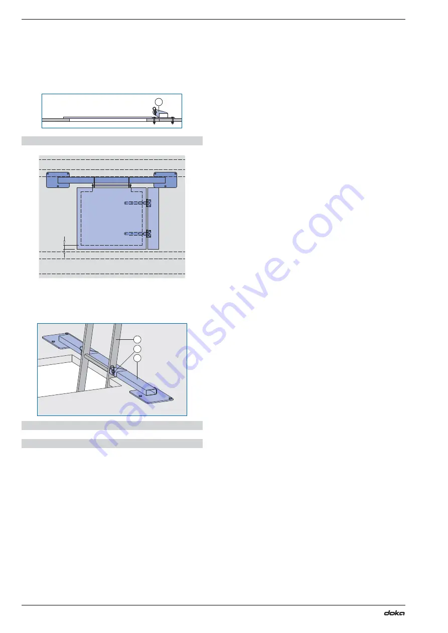
Page 161: ... mm b 800 mm c 50 mm d 500 mm Fix a Cover hinge SK 35cm to the manhole lid and the platform If a timber stop bar is screwed onto the platform decking behind the hinge the lid can be made to be self closing A Manhole B 70 60cm B System ladder XS 4 40m C Ladder bolt XS 98058 480 01 A B C 98058 481 01 c a b d CAUTION When choosing what type of manhole lid to use make sure that it has sufficient load ...

Page 162: ...M10x70 6 washers A 10 5 6 hexagon nuts M 10 not included with product e Overlap min 50 mm Guide the fixing bolt of the Ladder suspension SK through the rung of the ladder and secure on both sides with d4 spring cotters E Ladder suspension SK E Ladder suspension SK F System ladder XS 4 40m G Ladder bolt XS 98058 482 01 E 98058 481 02 e 98058 481 03 E F G ...

Page 163: ...ensions XS 2 30m can be fixed together in the same way Screw the Ladder adapter XS to the platform deck ing Fix the bottom of the ladder to the Ladder adapter XS Nuts bolts etc required for each Ladder adapter XS 4 square bolts M10x70 4 washers A 10 5 4 hexagon nuts M 10 Ladder cage Fix the Ladder cage XS 1 00m onto the next available rung The safety latches prevent the cage being accidentally lif...

Page 164: ... the gap with a flap Gap between two platforms a 50 mm Gap between platform and wall a 50 mm Important note Cover these gaps to prevent any small items from falling off A Platform decking B Rubber sheet 0 35x10 00m C Universal countersunk screw 5x50 washer 6 A Platform decking B Rubber sheet 0 35x10 00m C Universal countersunk screw 5x50 washer 6 98058 416 18 a A B C 98058 416 17 a A B C A Platfor...

Page 165: ...on the thickness of the decking 6 washers A10 5 6 hexagon nuts M 10 CAUTION When choosing what type of flap to use make sure that it has sufficient load bearing capacity It is forbidden to use 21mm or 27mm 3 ply sheeting for the manhole lid Use a 32mm web board or equivalent 21mm multi ply formwork sheets with non skid sur facing Use the Planking hinge 39cm A Raw sheet 3 S 31mm B Planking hinge 39...

Page 166: ...drail post 1 50m 98058 409 05 Screw on handrail post 1 50m Scaffold tube Guard rail board Dynamic pressure q ze Height of guard rail boards 15 cm 20 cm 1 1 kN m2 4 0 m 1 7 m 1 3 m 1 3 kN m2 3 4 m 1 5 m 1 1 m 1 7 kN m2 2 6 m 1 1 m 0 8 m A Screw on handrail post 1 50m B Screw on coupler 48mm 95 C Scaffold tube D Guard rail boards E Plank 5x20 cm Important note In this handrail post configuration gap...

Page 167: ...ctly onto the Raw sheet 3 S 38mm There is no need for a plank to distribute the loads Mounting the toeboard and scaffold tubes Attach a toeboard min 15x3 cm to the handrail post uprights with M10 square bolts Mount Scaffold tubes 48 3mm with the Screw on coupler 48mm 50 or attach guard rail boards to the handrail post uprights with M10 square bolts Important note Screw planks to the underside of t...

Page 168: ...he suspended stair tower provides easy access to the Platform SCP a safe up and down route between the working platform and the follow up platform and an emergency exit The stair tower is mounted to the girder grille of the Platform SCP Follow the directions in the Suspended stair tower 250 User Information booklet 98058 304 05 ...

Page 169: ...concrete plac ing boom can also be raised together with the Platform SCP The loads which occur during pouring are transferred into the structure via a project specific scaffold for the concrete placing boom The concrete placing boom is lifted by pulling up the lower base beam Pouring operations can continue while the Platform SCP is being lifted 98058 304 06 ...

Page 170: ...ppliances crane pallet stacking truck forklift truck To make the Doka skeleton transport box easier to load and unload one of its sidewalls can be opened Using Doka skeleton transport boxes 1 70x0 80m as storage units Max n of boxes on top of one another Using Doka skeleton transport boxes 1 70x0 80m as transport devices Lifting by crane Repositioning by forklift truck or pallet stacking truck The...

Page 171: ...stacking truck The forks can be inserted under either the broadside or the narrowside of the containers Max load 1500 kg Permitted imposed load 7900 kg Multi trip packaging items that each contain very different loads must be stacked with the heaviest ones at the bottom and the lightest ones at the top Rating plate must be in place and clearly leg ible A Slide bolt for fixing the partition Tr755 2...

Page 172: ...op Rating plate must be in place and clearly leg ible Outdoors on the site Indoors Floor gradient up to 3 Floor gradient up to 1 2 6 It is not allowed to stack empty pallets on top of one another How to use with bolt on castor set Always apply the fixing brake when the con tainer is parked When Doka stacking pallets are stacked the bottom pallet must NOT be one with a bolt on caster set mounted to...

Page 173: ... follow ing multi trip packaging items Doka accessory box Doka stacking pallets Follow the directions in the Bolt on castor set B Operating Instructions Max load 1000 kg Permitted imposed load 5530 kg Multi trip packaging items that each contain very different loads must be stacked with the heaviest ones at the bottom and the lightest ones at the top Rating plate must be in place and clearly leg i...

Page 174: ...tch for a connected hydraulic circuit has not been selected Remedy Switch off all pre selector switches Select the pre selector switch of the cylinder that did not move Press and hold down the Lift cylinder button until the platform has levelled itself Then switch on the remaining hydraulic circuits that are connected by actuating the pre selector switches Resume the Lifting the platform operation...

Page 175: ...elves to the pertinent fundamental health and safety stipulations of the relevant EC Direc tives The following harmonised standards were applied EN ISO 12100 2010 EN 349 1993 A1 2008 EN 982 1996 A1 2008 EN 60204 1 2005 Person authorised to compile technical documentation pursuant to European Directive on Machinery Annex II Ing Johann Peneder Josef Umdasch Platz 1 A 3300 Amstetten Amstetten 19 01 2...

Page 176: ... 581252000 Zwischenplatte WU30 F Pressure plate F 16 1 581253000 Druckplatte F Clamping plate U300 8 3 540289120 Klemmplatte U300 Joint plate U300 9 6 540289130 Zwischenplatte U300 Clamping plate WS10 V 4 5 540289150 Klemmplatte WS10 V Vertical profile 150 450 S355 227 0 581256000 Vertical profile 150 481 S355 234 0 581257000 Vertical profile 150 512 S355 245 0 581258000 Vertical profile 150 543 S...

Page 177: ...ger Lower latch 29 2 540289360 Untere Klinke Support SCP 64 0 583127000 Auflager SCP Quick locking strap 55cm 0 07 580787000 Gurtschnellverschluss 55cm Box for latch 15 0 11 5 540289370 Aussparungskasten 15 0 Upper cylinder connector SCP 150 0 583135000 Zylinderanschluss oben SCP Cylinder bolt d80x215 8 6 540289730 Zylinderbolzen D80 215 Fixing shoe 240 240 18 2 540289740 Startschuh 240 240 Galvan...

Page 178: ...ngitud 117 0 540289470 Geländerprofil IPB140 Joch Railing profile IPB140 transverse 106 5 540289471 Geländerprofil IPB140 Quer Clamping unit FRQ 50 B 1 9 540289490 Klemmung FRQ 50 B Clamping plate star 14 7 540289180 Klemmplatte Stern Platform cross double 15 4 540289755 Bühnenstern 2 fach Platform cross WS10 32 8 540289750 Bühnenstern WS10 Galvanised Length 24 cm Width 21 cm Galvanised Length 32 ...

Page 179: ...nier SK 35cm Screw on handrail post 1 50m 10 0 540451080 Anschraubgeländer 1 50m Fixing shoe A 2 9 540289920 Befestigungsschuh A Beam clamp U300 0 10 540289930 Trägerklammer U300 Beam clamp U300 double 0 50 540289935 Trägerklammer U300 doppelt Element suspender SK 3 9 583260000 Elementabhängung SK Head fixing plate SK 3 1 583261000 Kopfklemmplatte SK Element suspender 5 8 540289520 Elementabhängun...

Page 180: ... Elementhalter WS10 Corner holder Top50 5 9 540289570 Eckhalter Top50 Framax holder 6 8 540289560 Framax Halter Steel waling fixing WS10 1 5 540289550 Stahlwandriegelhalter WS10 Fixing angle 6 4 540289530 Justierungswinkel Double bolt D12 0 50 540289540 Doppelbolzen D12 Double fixing plate WS10 H 2 3 540289190 Doppelklemmplatte WS10 H Galvanised Width 92 cm Height 230 cm Galvanised Galvanised Galv...

Page 181: ...SCP B 400kN 813 5 583101000 Hydraulikzylinder SCP B 400kN Pair of hydraulic hoses 5 00m 5 3 580873000 Pair of hydraulic hoses 7 50m 7 3 580874000 Pair of hydraulic hoses 10 00m 9 4 580875000 Hydraulikschlauchpaar Hose clamp 14 20mm 0 02 583128000 Schlauchklammer 14 20mm Connection adapter S SCP 2 0 581647000 Anschlussadapter S SCP Connection adapter M SCP 2 0 581648000 Anschlussadapter M SCP Conne...

Page 182: ...4000 Multi purpose waling WS10 Top50 1 50m 29 7 580005000 Multi purpose waling WS10 Top50 1 75m 35 0 580006000 Multi purpose waling WS10 Top50 2 00m 38 9 580007000 Multi purpose waling WS10 Top50 2 25m 44 2 580008000 Multi purpose waling WS10 Top50 2 50m 48 7 580009000 Multi purpose waling WS10 Top50 2 75m 54 2 580010000 Multi purpose waling WS10 Top50 3 00m 58 9 580011000 Multi purpose waling WS1...

Page 183: ... 5 189939000 Doka beam H20 eco P 12 00m 62 4 189993000 Doka Träger H20 eco P Beam screw H 8 70 0 06 580117000 Riegelverschraubung H 8 70 Beam screw S 8 70 0 06 580116500 Riegelverschraubung S 8 70 Scaffold tube 48 3mm 0 50m 1 7 682026000 Scaffold tube 48 3mm 1 00m 3 6 682014000 Scaffold tube 48 3mm 1 50m 5 4 682015000 Scaffold tube 48 3mm 2 00m 7 2 682016000 Scaffold tube 48 3mm 2 50m 9 0 68201700...

Page 184: ...nch 30 0 43 582840000 U Combination wrench 32 0 75 582859000 V Combination wrench 36 0 75 582860000 W Combination wrench 41 1 5 582841000 X Ratchet ring wrench 17 19 0 47 581546000 Length 27 cm Y Ratchet ring wrench 22 24 0 59 581547000 Length 33 cm Z Fork wrench 50 0 98 581549000 Length 41 cm AA Reversible ratchet 1 2 0 73 580580000 Galvanised Length 30 cm AB Reversible ratchet 3 4 1 5 580894000 ...

Page 185: ...icles Bracing FRQ mm Verschwertung FRQ mm Bracing FL mm 8 5 540289840 Verschwertung FL mm Upper distance profile U300 mm Oberes Distanzprofil U300 mm Lower distance profile U300 mm Lower distance profile U320 mm Lower distance profile U350 mm Lower distance profile U380 mm Lower distance profile U400 mm Unteres Distanzprofil Multi trip packaging Doka skeleton transport box 1 70x0 80m 87 0 58301200...

Page 186: ...1442000 Universal Kletterkonus 20 0 Sealing sleeve K 20 0 0 03 581443000 Dichtungshülse K 20 0 Form ply protector 32mm 0 38 580220000 Schalhautschutz 32mm Cone screw B 7cm 0 86 581444000 Konusschraube B 7cm Stop anchor 20 0 17 5cm 90 0 93 581480000 Sperranker 20 0 17 5cm 90 Climbing cone SCP 20 0 7 3 581646000 Kletterkonus SCP 20 0 Sealing sleeve SCP 20 0 0 07 581650000 Dichtungshülse SCP 20 0 Gal...

Page 187: ...s frame hole plug A 38mm 0 005 589233000 Framax Xlife plus Ankerstopfen A 38mm Cone screw M36 SW50 9cm 1 5 581651000 Konusschraube M36 SW50 9cm Positioning screw SCP M36 3 4 581658000 Vorlaufschraube SCP M36 Positioning clamp M36 0 45 583132000 Vorlaufklemme M36 Galvanised Black Yellow Length 12 5 cm Diameter 7 7 cm Width across 50 mm Galvanised Length 40 cm Width across 55 mm Galvanised ...

Page 188: ...nd distributing formwork technology for use in all fields of the construction sector With more than 160 sales and logistics facilities in over 70 countries the Doka Group has a highly efficient dis tribution network which ensures that equipment and technical support are provided swiftly and profession ally An enterprise forming part of the Umdasch Group the Doka Group employs a worldwide workforce...

Reviews: