background image

44

999817902 - 10/2022 

Scaffold

User Information 

Ringlock

Suspended Scaffolding

The purpose of suspended scaffold is to optimize the 

amount of material at extreme height or when a sup-

ported scaffold is not possible.

Method of Scaffolding Suspension

There are different methods of suspending scaffolds 

from permanent structure, which includes both not lim-

ited to the following:
Methods of scaffold suspensions can utilize the Rin-

glock components with the combination of tube and 

couplers, and/or chain/wire rope.


Beam Clamps may be used to attach the Standard to 

the permanent steel beam at the bottom or top beam 

flange. When attaching the Standard to the steel 

beam, the suspension point may be on one side or 

both sides of the steel beam.


Box tie arrangement may be used to attach the per-

manent beam by utilizing tubes and couplers all 

around the existing structure.

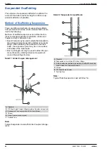
Detail 1: Girder Coupler Arrangement 

Note:

Typical Suspension Load with Girder Coupler Arrange-

ment.

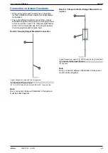
Detail 2: Suspended around Beam 

Note:

Typical Total Suspension Load with Box Tie.

A

Standard

B

D/F Right Angle Coupler (Supplementary Couplers as required)

C

Suspension Tube no more than 0.3m from I-Beam

D

I-Beam

E

Girder Coupler (used in pairs)

F

Scaffold Tube

A

Standard

B

Suspension no more than 0.3m from I-Beam

C

If lower loads are required a typical short Scaffold Tube can be 
used instead of a Ringlock Standard

D

I-Beam

E

D/F Right Angle Coupler

F

Scaffold Tube

Summary of Contents for Ringlock

Page 1: ... by Doka GmbH A 3300 Amstetten 999817902 10 2022 en GB Ringlock User Information Instructions for assembly and use Method statement by Doka GmbH A 3300 Amstetten ...

Page 2: ...2 999817902 10 2022 User Information Ringlock ...

Page 3: ...ffolding 41 Plank Arrangement 43 Raised Ledger System RLS 44 Suspended Scaffolding 46 Cantilever 48 Gaps in Platforms 50 Methods of Stabilising Scaffolds 52 Rebar Scaffold 53 Mobile Scaffolds 54 Ringlock Shoring 55 Erection Guidelines for 4 Leg Stair Tower 56 4 Leg Aluminum Stair Tower General Arrangement 57 4 Leg Aluminum Stair Tower Erection Guidelines Steps 60 Ringlock Aluminum Stair Tower 4 Le...

Page 4: ...hazard assessment and for the instructions given to users on how to prepare and utilise the system It does not substitute for these however Remarks on this booklet This document can be used as general Instructions for Assembly and Use Method Statement or be incorporated into site specific Instructions for Assembly and Use Method Statement The graphics animations and videos in this doc ument or app...

Page 5: ...checked at regular intervals to ensure that they are secure and in full working order In particular threaded connections and wedged con nections have to be checked and retightened as nec essary in accordance with activity on the jobsite and especially after out of the ordinary occurrences e g after a storm It is strictly forbidden to weld Doka products in par ticular anchoring tying components sus...

Page 6: ...the right to make alterations in the interests of technical progress Eurocodes at Doka The permissible values stated in Doka documents e g Fperm 70 kN are not design values e g FRd 105 kN It is essential to avoid confusing permissible values with design values Doka documents will continue to state the permissi ble values Allowance has been made for the following partial fac tors γF 1 5 γM timber 1...

Page 7: ...trademarked AT PAC Ringlock system which in turn conforms to European standards EN 12810 and EN 12811 Ringlock is also compliant with The National Access Scaffolding Confederation NASC Code of Practice for System Scaffold within the United Kingdom Please refer to table in the chapter Comparison of the article list of Doka and AT PAC The Ringlock Scaffolding System is certified by the Deutsches Ins...

Page 8: ...caffolding system Further possible assembly variants and applications can be found in the additional technical documents from Doka Doka s Ringlock modular scaffolding system enables users to Assemble use and dismantle temporary work scaffolding quickly and efficiently The Ringlock modu lar scaffolding system meets the requirements of EN 12810 and EN 12811 and has the German general building author...

Page 9: ...orm width and bay length are also available SW06 73 to SW06 307 CLADDING Maximum permissible heights and tie pat terns are given for both unsheeted debris netted and sheeted scaffolds For more information on products not found within this document or the Ringlock Brochure please consult your local Doka representative or online at www doka com Node capacities 1 65 Safety Factor The Ringlock modular...

Page 10: ...g on the Ringlock scaffold a hazard anal ysis must be carried out considering the special fea tures of the individual case The result must be recorded in a risk assessment and the personnel must be instructed Particular attention should be paid to technical protective measures against falls from a height and to the measures required for possible res cue operations If the use of personal protective...

Page 11: ... Swing Gate Employers have an obligation to ensure that Work at Height is Properly planned Appropriately supervised Done in a safe manner so far as is reasonably practicable Include planning for emergencies rescue Weather conditions do not jeopardise health and safety Before allowing people or materials on the Ringlock scaffold ensure that it has been erected correctly and complies with the specif...

Page 12: ... a Ringlock scaffold which is being erected or dismantled Never Remove ladders or staircases Never Overload the scaffold Never Undermine the scaffold by digging trenches or foundations under or adjacent to it Never Add sheeting or netting to scaffold without the approval of the scaffold designer Never Forklift loads directly onto access scaffold instead use a loading tower WARNING Never take risks...

Page 13: ...n to possible danger of falling between scaffolding and building Use only existing ladders or stairs for ascent and descent Keep the hatches closed in the Ladder Hatch Decks Leave a sufficiently wide passage on the deck ing when storing materials Do not jump off from the scaffold Do not endanger the stability of the structure by excavation Do not place any material on cantilever and on the brickgu...

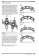
Page 14: ...er of 123mm and has been manufactured with 8 trapezoidal slots 4 small and 4 large The smaller holes represent the 90 degree angle at the Ledgers and Transoms are installed The larger trapezoidal holes accommodate the Diagonal Bay Braces If the needed the Ledgers can be installed in the larger holes allowing up to 15 degrees of rotation This pro vides added flexibility to clear obstacles when nece...

Page 15: ... connections whereas the larger opening enable connections at variable angles to be achieved Unless erecting a scaffold around a circular building structure align the Base Collar rosettes so that one of the small openings in the rosette points in the Ledger direction The small openings at right angles to the first will automatically align the Transoms at 90 degrees The larger openings are generall...

Page 16: ...s per EN 39 Scaffolding couplers per EN 74 Wood Plank per relevant European Standard Scaffolding couples can be connected to all Ø 48 3mm tubular Ringlock components with the exception of all Ringlock vertical Bay Braces When Wood Planks are lapped and used as working platform in conjunction with Ringlock System addi tional guardrails must be installed to meet the minimum guardrail height 95cm in ...

Page 17: ...mon Ringlock components used Most scaffold structures are made from these basic components yet the Rin glock system comes with a variety of accessories for all your scaffolding requirements A Side Bracket or Console Bracket B Standard C Starter Base Collar D Base Jack E Bay Brace F Ledger G Alum Stair Platform H Steel Plank I Toeboard ...

Page 18: ... B Starter Base Collar C Standard D Bay Brace E Ledger F Guardrail Ledger G Wall Tie H Toeboard I Steel Plank J Alum Hatch Deck with Ladder A Alum Stair Platform B Alum Stair Outer Guardrail C Alum Stair Filler Guardrail D Alum Stair Inner Guardrail E Landing Ledger with Spigot ...

Page 19: ...colourcoded identification label This process allows the scaffolder to easily match particular components for each size of the bay to be erected For example An Green Ledger 2 57m will work with an Green Diagonal and an Green Plank 981 01 79 307 981 01 79 308 981 01 79 309 981 01 79 310 981 01 79 311 981 01 79 312 981 01 79 313 981 01 79 314 981 01 79 315 981 01 79 316 ...

Page 20: ...e scaffold are required check the requirements of the local authority with respect to what must be shown on the drawings load rating erection dismantling instructions etc All equipment should be inspected prior to use to ensure that it is in good condition and is serviceable Damaged or deteriorated equipment must not be used Avoid storing or handling scaffold components below or close to electrica...

Page 21: ... Consider the job at hand and ensure that nothing has been missed Never be taken in by the Big Risk and miss other potential problems such as trip hazards people working nearby possibility of dropping objects etc Once you start the erection work Never work outside the scope of the Risk Assess ment Always stop work and re assess if conditions change or if additional hazards which are not included i...

Page 22: ...al protective equipment against falls from a height in its current ver sion apply lt should be noted that when using when PPE there must be adequate clearance below the standing level depending on the length of the lanyard used and the ground and or obstacle below Safety harness connection points can be made either on ledgers up to 2 m above the standing level or on the rosettes in the small or la...

Page 23: ...our Shock Absorbing Lanyard Below represents where you can safety attach a Scaf fold hook snap hook Connection locations shown in Red are not suitable for fixing to The anchorage points shown in Green are to support Shock Absorbing Lanyard fall arrest equipment 98179 254 01 ...

Page 24: ...6 lift can be attached to a single Standard Ringlock Rosette It is recommended to connect the Scaffold Hook to the large trapezoidal holes to provide a suitable anchor point for the appropriate safety harness DO NOT attach the safety harness lanyard to itself around a Standard because the edge of the rosette may cut the fabric or it may slip over the rosette to the next lower rosette increasing th...

Page 25: ...lation and safe use of fall protection equipment as required by Work at Height Regulations Contractors and their employees must comply with the Work at Height Regulations Scaffolders should use an appropriate safety har ness at all times such that the individual stays fully protected from falling when working at heights Scaf folders should use suitable safe zones as per TG4 current revision at all...

Page 26: ...he proper installation of Planks ensures the platform is free of gaps larger than 1 25mm Toeboards Install the Ringlock Toeboards to protect workers from falling hand tools debris and other small objects These fit behind the wedges and interlock together Ledgers The Ringlock Ledgers act as guardrails and are located 19 7 0 5m and 3 3 1 0m above the working plat form meeting the requirements of loc...

Page 27: ...sible adjustment of the extension length Then connect the longitudinal and transverse ledgers in the small openings of the rosette by means of loosely inserted wedges Step 2 Using a spirit level the scaffold is levelled horizon tally by turning the adjusting nuts on the base jack spindles accordingly The squareness of the bays is checked by measur ing the diagonals The insertion of planks in this ...

Page 28: ...ces are installed by first sliding on the lower bay brace head and loosely inserting the wedge in the large opening of the rosette Then the upper bay brace head is pushed onto the rosette in the next scaffold level The bay brace is fixed by hammering with a 500g hammer until it is fixed If possible they should always be mounted on the outside of the scaffold at nodes stiffened by ledgers Depending...

Page 29: ... additional level is required When no additional level is required If no additional level is required 1 0m long vertical posts can be added as guardrail posts on the inner side and at the end of the scaffold top level The decking level can now be accessed with the installed guardrails In order to have working access toe boards are required to be installed The steel planks used for the assembly at ...

Page 30: ... level of the first Sole Board 2 When the ground is more than 500 mm below high est ground level set the Base Jack adjusting han dle near to the bottom of the thread and fit the Base Collar Introduce a Standard and wind up the thread on the Base Jack until the second rosette in the lift is level with the previous Standard Introduce the Ledger to fix the Base jack base Collar and Stand ard in place...

Page 31: ...nks can be installed on the Lattice Girder direction if steel planks are to be installed parallel to the Lattice Girder then the Girder Transom must be used Girder Transoms are available with and without side brackets Girder Transom Installation Step 1 Install the Lattice Girders in the rosettes of the Standards by installing the wedges of the connection heads with a 500g hammer until the hammer b...

Page 32: ...dgers Step 3 After installing the aluminum staircase and engaging the wind latch the outer railing can be installed and the stringers can be wedge from the secured first level Step 4 After assembly of the aluminum staircase the lead ing side protection on the staircase access panel can be removed and now the next scaffolding level can be installed NOTICE It should be noted that the fall through pr...

Page 33: ... level of the staircase the longitudinal ledger at the deck level next to the stair platform is replaced by the landing ledger with spigot This has a welded spigot which together with a 1m vertical stile as an end post guarantees the side pro tection of the staircase landing ...

Page 34: ...ening the scaffold by means of external brackets no access decks may be fitted in the bay widened by the brackets Internal Incline Ladder Access This Ladder Access involves installing inclined Ladders within the scaffold and securing them near the bottom of the longitudinal Ledger and to the top of the guard rail Methods of securing the Ladder may include the use of Ladder clips or hooks Add the L...

Page 35: ...e topmost scaffold level If required extend the exterior Standards up an additional 1m so that the protective wall has a height of more than or equal to 2m from the top planked level For all assembly variants splice joints of the Standards must not be located at the top planked level Additional ledgers which are connected to the upper most rosette of the additional standards form the frame for the...

Page 36: ...The outside Ledger at platform level has been replaced with a Console Bracket In order to create the Guardrail a Standard is attached to the terminal on the Console Bracket This minimizes the number of components in comparison to the layout above Bracing and Edge Protection removed for clarity NOTICE When dealing with an internal or external cor ner it is imperative that a 3 part side protection i...

Page 37: ...at platform level has been replaced with a Console Bracket In order to create the Guardrail a Standard is attached to the terminal on the Console Bracket An equivalent size bay to match the internal cantilever platform has been added A fully closed corner has been developed with internal cantilevered platforms and minimizes the number of components in comparison to the lay out above Bracing and Ed...

Page 38: ...e and Clamp used on the inside Standards As illustrated Ringlock bays can be joined at angles using the 0 15m Ledger Scaffolding around circular structures requires the use of Tube and Clamp to join Ringlock bays together and to fix guardrails on the outside face of the Ringlock façade Use suitable material to span the gap between the platforms Typically LVL or Wood Scaffold Planks are used depend...

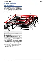
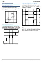
Page 39: ...age scaffolding to pro vide safe areas of work Fully decked bays This method assumes that the full lift of the birdcage will be completely decked out pro viding an internal safe working area Only the perim eter of the birdcage will require suitable guardrails to provide safe working zones Partially Decked bays This method assumes that suitable areas will be decked with guardrails to pro vide erect...

Page 40: ...g is required in bothdi rections on all 4 corners Bracing is to be full height of the scaffold and decking is assumed to be top lift only Larger than 6 Bay Long by 6 Bay Wide For Birdcages 6x6 Bays and larger bracing is required both directions no greater than 5 bays in any direction Bracing is to be full height of the scaffold and decking is assumed to be top lift only Note For any alternate bird...

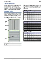
Page 41: ... 2 07 2 57 3 07 0 73 Ledger Ledger Ledger Ledger Ledger Ledger Ledger 1 09 Ledger Ledger Ledger Ledger Ledger Ledger Ledger 1 40 Ledger Ledger Ledger Ledger Ledger Ledger Ledger 1 57 Ledger Ledger Ledger Ledger Ledger Ledger Ledger 2 07 Ledger Ledger Ledger Ledger Ledger Ledger Ledger 2 57 Ledger Ledger Ledger Ledger Ledger Ledger Ledger 3 07 Ledger Ledger Ledger Ledger Ledger Truss Truss Bearer T...

Page 42: ... Ledger Ledger Ledger 1 57 Ledger Ledger Ledger Ledger Ledger Ledger Ledger 2 07 Ledger Ledger Ledger Ledger Ledger Ledger Ledger 2 57 Ledger Ledger Ledger Ledger Truss Truss Truss 3 07 Ledger Ledger Truss Truss Truss Truss Truss Bearer Transom Length m Bay Length m 0 73 1 09 1 40 1 57 2 07 2 57 3 07 0 73 Ledger Ledger Ledger Ledger Ledger Ledger Ledger 1 09 Ledger Ledger Ledger Ledger Ledger Ledg...

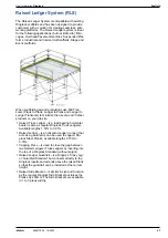
Page 43: ... your job site Raised Truss Ledger is a load bearing horizontal bearer same as regular Ringlock Truss Ledgers Available lengths 1 57m to 3 07m Raised Ledger is a horizontal Ledger runner that acts as a guardrail or can be used to support Rin glock Steel Planks Available lengths 0 73m to 3 07m Capping Piece is used to close the gap between two Raised Ledgers Truss Ledgers by inserting into the top ...

Page 44: ...lange When attaching the Standard to the steel beam the suspension point may be on one side or both sides of the steel beam Box tie arrangement may be used to attach the per manent beam by utilizing tubes and couplers all around the existing structure Detail 1 Girder Coupler Arrangement Note Typical Suspension Load with Girder Coupler Arrange ment Detail 2 Suspended around Beam Note Typical Total ...

Page 45: ...nded due to the lower capacity then Hanging Standard double bolt Detail 3 Hanging Spigot Standard Connection Typical Suspension Load with this Arrangement Note Every connection between Standards in Suspension must be bolted together Detail 4 Crimped or Bolted Spigot Standard Con nection Typical Suspension Load with 2 XM12 Grade 8 8 Hex Nut and Bolt Note Every connection between Standards in Suspen...

Page 46: ...e Bracket 1 09m Extension 0 39m Side Bracket for 1 x 320mm plank 0 73m Side Bracket for 2 x 320mm plank or 1 x 640mm Ladder Hatch Plank or Aluminum platform Stair 1 09m Console Bracket for 3 x 320mm plank or 1 x 640mm Ladder Hatch Plank or Aluminum platform Stair 1 x 320mm plank Cantilever with Standard Ledger an Bay Braces The Ringlock System can accommodate cantilevers by the adding additional B...

Page 47: ...Ringlock cantilever it must be designed specifically for each application The lattice girder should be installed using at minimum 4 right angle couplers attached to 2 Ringlock Standards back span In order to install a lat tice girder at the cantilever the Ringlock Standard must be extended 1m below the working level Counter weight and or tie s shall be assessed to resist over turning as required A...

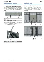
Page 48: ...thod utilizes Ringlock ledgers installed with the Horizontal Rosette coupler Ledger to Plank Transoms The Ledger to Plank Transom method is similar to the Mid Transom method except the Ledger to Plank Tran som method secures to a Ledger at one end and rests on a Ringlock Plank at the other The Ledger to Plank Transom method is particularly useful when openings are required next to the edge of a ba...

Page 49: ... of the side rail there are two holes To prevent uplift or dis placement of the Infill Plank use the two holes to secure the Infill Plank to a Ledger Gap Filler Plank Ensure that the Gap Filler Plank is adequate for the imposed duty ratings on the platform The illustration shows the use of Gap Filler Plank is lapped over Ringlock Planks Each Gap Filler Plank must be secured at each end with plasti...

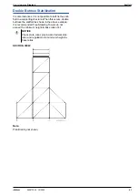
Page 50: ... tie and tubes onto the Ledgers Note Wall anchor not shown Single Butress Stabilization A Buttress is an extension of the primary scaffold Install a Buttress to expand the width of the base and to provide support to the free standing structure with a 4 1 minimum height to base ratio Plan brace the buttress every fourth bay along the façade Install a butt tie on the scaffold to prevent it from incl...

Page 51: ...old to a supporting structure When this occurs double buttress the scaffold as shown in the above example It is recommended Free Standing Towers do not exceed the minimum height to base ratio of 4 1 SECTION VIEW Note Plan Bracing not shown NOTICE Check state local provincial or federal stat utes and regulations for minimum height to base ratios ...

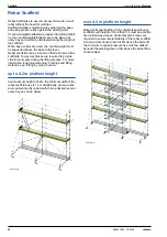
Page 52: ...required to provide structural integrity during the lifting process For more information regarding temporary bracings and lifting methods see Lifting by crane section up to 4 2 m platform height At a maximum height of 4 2m the minimum width of the rebar scaffold base is 1 4m Additionally pressure ties are required directly underneath the top decked level at every bay as shown below over 4 2 m plat...

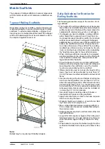
Page 53: ...ructure When a rolling scaffold is in proximity to energized electrical equipment the wheels must be fitted with nonconductive resilient tires Always lockout and tagout all electrical hazards Fit each wheel or Caster on a mobile scaffold with brakes or other locking devices to prevent rolling and swiveling when the scaffold is in use The Casters must be securely attached to the scaffold lf Base Ja...

Page 54: ...et the demands of construction projects around the world and may require the use of Heavy Duty Base Jacks and U Heads Lift heights can be adjusted to minimize the number of components required to suit load resistance requirements Shoring Tower Assembly Exploded View A U Head Assembly Dependent on Load Requirements B Standard open ended C Bay Brace 1 0m D Standard with Spigot E Ledger F Bay Brace 2...

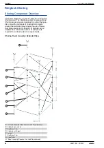
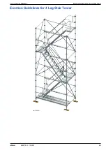
Page 55: ...User Information Ringlock Erection Guidelines for 4 Leg Stair Tower 55 999817902 10 2022 Erection Guidelines for 4 Leg Stair Tower 98179 236 01 ...

Page 56: ...onstructed with Ringlock scaffolding components In the following the 4 legged platform stair tower is pre sented which consists of standard components of the Ringlock scaffolding system and can be integrated into an existing scaffolding or may also be used inde pendently lf required access to each scaffolding level can be provided Further assembly variants can be found in the corresponding technic...

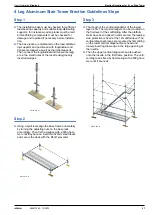
Page 57: ... a spirit level align the base frame horizontally by turning the adjusting nuts on the base jack accordingly Then fix the wedges with a 500g ham mer until they bounce insert two 320mm steel decks and secure the deck with the lift off preventer Step 3 The length of the vertical standards of the lowest layer is 3m The required ledgers can be mounted on the first level of the scaffolding After the pl...

Page 58: ...ng 320mm can be used The ledgers in the first scaffold position provide the necessary fall protec tion here Step 5 After the installation of the guardrail a temporary level is formed from two steel layers on the opposite side of the stair landing As with the tubular ledgers and diagonals the wedges of the ridge rail are wedged against the rosettes until they bounce The ledgers of the top layer can...

Page 59: ...s required Suitable safety harness connection points are located in the Safety Harness Connection Points section From the stair landing and the temporary working level the other vertical standards 2m the vertical diagonals and the ledgers of the next scaffold level are installed On the inside of the staircase the inner guardrail is attached and secured to the stringers with the hammerhead screws 9...

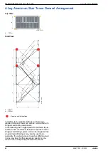
Page 60: ...on Ringlock Ringlock Aluminum Stair Tower 4 Leg Layout The below detail is for a 4 Leg Stair Tower see Rin glock Stair Tower 4 Leg Quantity Lists Plan d 1 40 m End Elevation e 1 40 m a 2 57 m c 2 00 m 98179 249 01 d 98179 250 01 e 98179 238 01 a c c c Denotes wall tie locations ...

Page 61: ... Base jack 60cm 4 301020000 Base collar 4 301011000 Standard 1 00m crimped spigot 1 301012000 Standard 2 00m crimped spigot 4 301013000 Standard 3 00m crimped spigot 8 301031405 Ledger 1 40m 15 5 301032575 Ledger 2 57m 15 2 301061405 Bay brace 200 140cm 5 2 301062575 Bay brace 200 257cm 6 2 308031405 Steel plank 32 140cm 2 308032575 Steel plank 32 257cm 2 316012575 Platform Stair 2 57m 3 1 3160700...

Page 62: ...62 999817902 10 2022 Erection Guidelines for 10 Leg Stair Tower User Information Ringlock Erection Guidelines for 10 Leg Stair Tower 98179 224 01 ...

Page 63: ...these being the Stringer and the Treads It is not normally necessary to erect the tower with a crane After the Stringers have been assembled the Treads should be installed from bottom to top Double Guard rails around the landings guarantee stability and safety The landings are constructed from steel Planks and fit ted out with Toeboards Every Ringlock Scaffold and Stair Tower needs to be tied to a...

Page 64: ... loads The users of the stairs need to be aware that any changes to the scaffold must be properly engineered and erected in accordance with Doka and the Build ing Regulations for landings and stair arrangements etc It is recommended that routine checks form part of your everyday procedures to ensure that compo nents have not been removed or have been incor rectly assembled after they had been remo...

Page 65: ...in place on both outside bays three 320 mm wide steel Planks 2 07m long Step 3 Erect 3 0m Standards onto each base Collar and Jack and assemble the Ledgers and Transoms for the first lift Also assemble the Braces on the two outer sides Next assemble the Stair Stringers These lock into the rosettes at the top and the bottom of the plat forms and will also act as braces to each side of the scaffold ...

Page 66: ...Toeboards on the first landing Use the Scaffold Step to assemble a temporary plat form and single advanced Guardrail such that this can be used to erect the second landing If necessary an opening can be left in this platform to allow access by ladder The opening is formed using a Plank to Ledger Transom and a 1 09m Plank If necessary follow the guidance provided in Ladder Access section The tower ...

Page 67: ... from bottom to top Assemble the Planks on the next landing Step 8 The Stair Tower is complete after the assembly of 1m Standards on the third landing Guardrails Using Ledgers along the stair and on the third landing and Toeboards on the third landing The tower is now complete up to the third lift Continue with is method until the full height of the Stair tower is reached For notes on dismantling ...

Page 68: ...tion Ringlock Ringlock Stair Tower 10 Leg Layout Below is the General Arrangement for the Ringlock 10 Leg Steel Stair See Stair Tower 10 Leg Quantitiy Lists Plan d 2 07 m End Elevation e 1 04 m a 1 09 m b 2 07 m c 2 00 m 98179 225 01 d 98179 235 01 e e 98179 234 01 a b a c c c ...

Page 69: ... m 306010600 Base jack 60cm 10 301270000 Starter base collar 10 301011000 Standard 1 00m crimped spigot 5 301012000 Standard 2 00m crimped spigot 10 301013000 Standard 3 00m crimped spigot 20 301031045 Ledger 1 04m 12 2 301031095 Ledger 1 09m 32 10 301032075 Ledger 2 07m 26 7 301062075 Bay brace 200 207cm 18 6 308032075 Steel plank 32 207cm 16 4 308401045 Toeboard 2 4 104cm 1 308402075 Toeboard 2 ...

Page 70: ...d under Ringlock rosettes with a check clamp fitted above the rosette Reference Lift ing Arrangement Use ropes or other devises to guide the scaffold and to prevent its rotation Lifting Arrangements Scaffolding can be transported by crane if it has been designed accordingly When designing and erecting lift ing scaffolds it is recommended but not limited to the following Base jack must be secured t...

Page 71: ...ing Temporary Bracing Bracing is required prior to each lift to minimize dis placement and torsion of the scaffold in any direction to prevent displacement and rotation during lifting Temporary Bracing is job specific and is dependent on the lift arrangement and rigging location Please refer to an Doka technical representative for the proper design and configuration of any Temporary Bracing on any...

Page 72: ...r Standard This type of anchoring can only transmit forces at right angles to the facade Long scaffold wall tie tube with two normal couplers on both Standards By connecting the long scaffold wall tie tube to both standards this type of anchoring also helps with the load transfer of forces parallel to the facade V Anchor Triangular Anchor Either connect both scaffold wall tie tubes to the inner st...

Page 73: ...ED V 3URWHFWLYH ZDOO VWRUH IXOO DQFKRUHG QFKRU SODQH RIIVHW E FP SRVVLEOH UDFLQJ 7UDQVRPV LQVLGH DQG RXWVLGH LQ HYHU VFDIIROG VWRUH 7UDQVRP DV KDQGUDLO SRVW RPPHQW QVWDOODWLRQ RI WKH SURWHFWLYH ZDOO ZLWK VWDQGDUGV P 9 DQFKRU 6FDIIROG KROGHU I VDIHW QHWWLQJ LV XVHG IRU WKH SURWHFWLYH ZDOO SDUW HGJH SURWHFWLRQ FRQVLVWLQJ RI WRHERDUG LQWHUPHGLDWH SRVW DQG KDQGUDLO SRVW LV QHFHVVDU 1 GJH SURWHFWLRQ FR...

Page 74: ...IXOO DQFKRUHG QFKRU SODQH RIIVHW E FP SRVVLEOH UDFLQJ 7UDQVRPV LQVLGH DQG RXWVLGH LQ HYHU VFDIIROG VWRUH 7UDQVRP DV KDQGUDLO SRVW RPPHQW QVWDOODWLRQ RI WKH SURWHFWLYH ZDOO ZLWK VWDQGDUGV P 6FDIIROG KROGHU I VDIHW QHWWLQJ LV XVHG IRU WKH SURWHFWLYH ZDOO SDUW HGJH SURWHFWLRQ FRQVLVWLQJ RI WRHERDUG LQWHUPHGLDWH SRVW DQG KDQGUDLO SRVW LV QHFHVVDU 1 GJH SURWHFWLRQ FRPSRQHQWV DUH VKRZQ RQO LQVRIDU DV VW...

Page 75: ... ORVHG IDoDGH 8QFODG VFDIIROG ORDG FODVV 1 P 2 W SH OHGJHU IRU VWDLU H LW ORVH XS RRW DUHD VWDLUZD P P QFKRUDJHV VDPH DV IRU FRUUHVSRQGLQJ FRQILJXUDWLRQV DV VKRZQ LQ QQH 3DJH DQG 3DJH QR RWKHU DGGLWLRQDO PHDVXUHV QHHGHG µ 7 3 5 1 2 PRGXODU V VWHP 8QFODG VFDIIROG EDVLF FRQILJXUDWLRQ DQG EUDFNHW FRQILJXUDWLRQ VWDLUZD ED OHQJWK P QQH 3DJH P ...

Page 76: ...3DLUV RI DQFKRUV FRQQHFWHG ZLWK QRUPDO FRXSOHUV WR WKH LQVLGH VWDQGDUGV LQ D 9 VKDSH DW DQ DQJOH RI DSSUR LQ WKH IUDPH SODQH QVWDOODWLRQ RI WKH 9 DQFKRUV RWK VFDIIROG KROGHUV RQ WKH LQVLGH VWDQGDUG RU LUVW VFDIIROG KROGHU RQ WKH LQVLGH VWDQGDUG DQG VHFRQG VFDIIROG KROGHU RQ WKH ILUVW VFDIIROG KROGHU µ 7 3 5 1 2 PRGXODU V VWHP QQH 3DJH QFKRUDJHV 6FDIIROG KROGHU 9 DQFKRU ...

Page 77: ...been obtained and always check the Risk Assessment and sign to sig nify your understanding It is recommended that you check your scaffold tools each day before work to ensure that all parts are in good condition if you discover or suspect any defects report them immediately to your Company management Do not use faulty equipment Be aware and make your workmates aware of any potential hazards near y...

Page 78: ...Accidents involving ladders frequently occur within our industry and account for many serious injuries Because the ladder is regarded as one of the most basic forms of access the dangers are not always anticipated Inspect ladders each time before they are used and report defects to your management Ensure they are straight with no obvious defects Do not use defec tive ladders Set ladders on a firm ...

Page 79: ...rsonnel ALWAYS keep yourself clear when hoisting scaffold ing components Never stand directly under the load Faults to look for in a Gin Wheel No certification No Safe Working Load stamped on the wheel Split pin missing Dents in the main body which will prevent smooth operation of the rope Only ring type gin wheels are permitted Faults to look for in a Rope No certification Rope is sleeved with an...

Page 80: ...d passersby should take top priority dur ing dismantling Before starting the dismantling procedure inspect the entire scaffold to ensure that it is still structurally sound that is no parts have been damaged or removed that would endanger workers on the scaf fold If any such damage or missing part is seen those parts must be replaced before commencing the operation Do not remove a scaffold tie or ...

Page 81: ...0 x 1 40m 4 7 301061575 Bay brace 200 157cm 01 06 157 50 Bay Brace 2 0 x 1 57m 5 2 301062075 Bay brace 200 207cm 01 06 207 50 Bay Brace 2 0 x 2 07m 6 10 301062575 Bay brace 200 257cm 01 06 257 50 Bay Brace 2 0 x 2 57m 8 5 301063075 Bay brace 200 307cm 01 06 307 50 Bay Brace 2 0 x 3 07m 10 1 301070735 Bay brace 150 73cm 01 07 073 50 Bay Brace 1 5 x 0 73m 2 5 301071045 Bay brace 150 104cm 01 07 104 ...

Page 82: ...edger 1 09m 01 68 109 00 Raised Ledger System Ledger 1 09m 3 7 301681405 RLS ledger 1 40m 01 68 140 50 Raised Ledger System Ledger 1 40m 4 7 301681575 RLS ledger 1 57m 01 68 157 50 Raised Ledger System Ledger 1 572m 5 2 301682075 RLS ledger 2 07m 01 68 207 50 Raised Ledger System Ledger 2 07m 6 10 301682575 RLS ledger 2 57m 01 68 257 50 Raised Ledger System Ledger 2 57m 8 5 301683075 RLS ledger 3 ...

Page 83: ...olt SW21 05 03 200 50 Spigot Adapter Clamp Bolt 21mm Nut UK 305082003 Girder spigot adapter clamp SW23 05 08 200 30 Girder Spigot Adapter Clamp 2 23mm Nut AU 305082004 Girder spigot adapter clamp SW22 EU 05 08 200 40 Girder Spigot Adapter Clamp 2 22mm Nut EU 305082005 Girder spigot adapter clamp SW21 05 08 200 50 Girder Spigot Adapter Clamp 2 21mm Nut UK 306010600 Base jack 60cm 06 01 060 00 Base ...

Page 84: ...ng gate galvanized SW21 10 15 200 50 Adjustable swing gate galvanized SW21 310189003 Swing gate with toeboard 900 SW23 10 18 900 30 Swing gate with toeboard 900 SW23 311022003 A type ladder bracket SW23 11 02 200 30 A Type Starter Bracket Ladder Bracket 23mm 311090243 Steel ladder AS1892 2 40m 11 09 024 30 Steel Ladder AS 1892 2 4m 311090303 Steel ladder AS1892 3 00m 11 09 030 30 Steel ladder AS18...

Page 85: ...28 46 060 00 Screw jack U Head 60cm 12 329142200 Heavy duty shoring adapter 29 14 220 00 Heavy Duty Shoring Adapter 335020000 Pigtail pin 35 02 000 00 Pig Tail Pin 335030000 Toggle pin 35 03 000 00 Toggle Pin 335040000 Spigot for hanging scaffold 35 04 000 00 Spigot for Hanging Scaffold 335150025 Spring pin 35 15 002 50 Spring Pin M12 338180023 Wall tie bracket double 38 18 002 30 Wall Tie Bracket...

Page 86: ...10 Anfangsstück kurz Castor wheel 10kN 7 0 307070100 Lenkrolle 10kN Castor wheel 10kN no screwjack 5 2 307090100 Lenkrolle 10kN ohne Fußspindel 4 way screw jack head 60cm 7 2 328450600 Vierwegkopfspindel 60cm Screw jack U head 60cm 6 8 328460600 Kopfspindel 60cm Spring pin 0 07 335150025 Rohrklappstecker Toggle pin 0 07 335030000 Klinkenstecker Pigtail pin 0 12 335020000 Fallstecker Lifting lug SW...

Page 87: ...binder für Hängegerüst Ledger 0 15m 1 2 301030150 Ledger 0 39m 2 1 301030395 Ledger 0 73m 3 3 301030735 Ledger 1 04m 4 4 301031045 Ledger 1 09m 4 5 301031095 Ledger 1 40m 5 6 301031405 Ledger 1 57m 6 2 301031575 Ledger 2 07m 8 0 301032075 Ledger 2 57m 9 8 301032575 Ledger 3 07m 11 6 301033075 Riegel Truss ledger 1 40m 9 4 301181400 Truss ledger 1 57m 10 4 301181575 Truss ledger 2 07m 13 8 30118207...

Page 88: ...Plan brace 307 73cm 12 0 301840735 Plan brace 257 109cm 10 6 301831090 Plan brace 257 73cm 10 2 301830735 Plan brace 207 109cm 9 0 301821090 Plan brace 207 73cm 8 5 301820735 Plan brace 157 109cm 7 4 301811090 Plan brace 157 73cm 6 8 301810735 Horizontaldiagonale Lattice girder 5 14m no spigot 55 2 301165145 Lattice girder 6 14m no spigot 64 9 301166145 Lattice girder 7 71m no spigot 82 3 30116771...

Page 89: ... 57m 4 8 308401575 Steel toeboard yellow 2 07m 6 1 308402075 Steel toeboard yellow 2 57m 7 4 308402575 Steel toeboard yellow 3 07m 8 7 308403075 Stahl Bordbrett gelb Toeboard retaining clamp SW21 0 74 304160015 Toeboard retaining clamp SW22 EU 0 74 304160014 Toeboard retaining clamp SW23 0 74 304160013 Bordbretthalter Infill plank 0 73m 2 8 308070735 Infill plank 1 09m 4 5 308071095 Infill plank 1...

Page 90: ...deck 100cm 23 5 319021005 Alum hatch deck 157cm 25 7 319021575 Alum hatch deck 207cm 30 0 319022075 Alu Durchstieg Ladder for hatch deck 1 57m 6 0 318081575 Leiter Gerüstbelag 1 57m Alum ladder for hatch deck 32 6 319050015 Alu Etagenleiter Aluminium ladder 2 40m 7 2 314012400 Aluminium ladder 3 60m 10 8 314013600 Aluminium ladder 4 80m 14 4 314014800 Aluminium ladder 6 00m 18 0 314016000 Alu Leit...

Page 91: ...0 307cm 16 0 316053075 Alu Innengeländer verlängert Alum stair outer guardrail 200 257cm 16 8 316062575 Alum stair outer guardrail 200 307cm 18 4 316063075 Alu Außengeländer Guard rail standard Crazy Leg 1 63m 8 2 301311630 Geländerstiel gekröpft 1 63m Adjustable swing gate SW21 8 7 310012005 Adjustable swing gate SW22 EU 8 7 310012004 Adjustable swing gate SW23 8 7 310012003 Schwingtüre verstellb...

Page 92: ...lt horizontal SW22 EU 0 84 301300014 Rosette clamp T bolt horizontal SW23 0 84 301300013 Lochscheibe T Bolzen horizontal RA adapter clamp SW21 1 6 305012005 RA adapter clamp SW22 EU 1 6 305012004 RA adapter clamp SW23 1 6 305012003 Keilkopfkupplung starr 90 Swivel adapter clamp SW21 1 8 305022005 Swivel adapter clamp SW22 EU 1 8 305022004 Swivel adapter clamp SW23 1 8 305022003 Keilkopfkupplung dr...

Page 93: ...tube 48 3mm m 3 6 682001000 Gerüstrohr 48 3mm Swivel coupler 48mm 1 5 582560000 Drehkupplung 48mm Normal coupler 48mm 1 2 682004000 Normalkupplung 48mm Reversible ratchet 3 4 1 5 580894000 Umschaltknarre 3 4 Box nut 22 3 4 L 0 22 582844000 Stecknuss 22 3 4 L T bolt M14 for coupler 0 10 698009004 T Bolzen M14 für Kupplung RLS capping piece 0 95 301640010 RLS Geländerkopf RLS exterior guardrail post...

Page 94: ...rmation Ringlock Girder transom 0 73m 7 6 301650735 Girder transom 1 09m 8 9 301651095 Trägerriegel U ledger 0 73m 3 2 301040735 U Riegel 0 73m Girder transom 0 73m inside bracket 10 6 301670735 Girder transom 1 09m inside bracket 11 8 301671095 Trägerriegel Innenkonsole ...

Page 95: ...er Information Ringlock 95 999817902 10 2022 Note Articles with the following designation SW21 Available in MEA and LATAM SW22 Available in EU SW23 Available in EAP SW Nut size Product under DIBt Approval ...

Page 96: ...nd distributing formwork technology for use in all fields of the construction sector With more than 160 sales and logistics facilities in over 70 countries the Doka Group has a highly efficient dis tribution network which ensures that equipment and technical support are provided swiftly and profession ally An enterprise forming part of the Umdasch Group the Doka Group employs a worldwide workforce...

Reviews: