background image

52

999808702 - 11/2019 

General

User Information 

Load-bearing tower Staxo


100


eco

Inclination adjustment

If the superstructure or the ground are 

inclined at an 

angle of 1% or more

, slope compensation must be 

provided.

using Wedges for screw-jack


.....


%

These prefabricated birch plywood wedges make it 

possible to stand load-bearing towers in the perpendic-

ular on surfaces with various inclinations, even when 

utilising the full leg load.

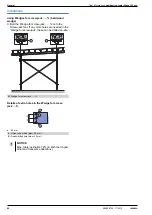
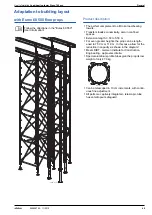
Inclined superstructures

Securing the superstructure at angles greater than 

12%:

Connect the head-plate to the longitudinal beam 

(e.g. with Locking rod 15.0 330mm and Super plate 

15.0 or Angle anchor plate 12/18)

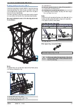
Inclined ground surface

using Staxo wedge support WS10

Used with timber wedges, this component provides 

angle adjustment to floor-slab constructions with a 

max. inclination of 45°.
Bolted into the multipurpose waling, this wedge support 

prevents the timber wedges slipping and ensures that 

the loads are safely transferred.

Note:

If the legs of the load-bearing tower have to be located 

outside the pattern of drilled holes in the multi-purpose 

waling, then a suitable 20


mm diam. hole must be 

drilled in the web of the waling.

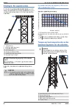
using Staxo wedge support WU12/14

Same function as Staxo wedge support WS10, except 

that it is suitable for being pinned to a 12


cm or 14


cm 

high waling.
The wedge support is labelled '12' and '14' on the 

respective sides, to ensure that it is always correctly 

positioned.

CAUTION

Excessively steep wedges may slip away!

Maximum inclination: 20%!

For this reason, wedges must NOT be placed 

on top of one another in an attempt to compen-

sate for inclinations that are greater than 20%.

A

Wedge for screw-jack


.....


%

B

Locking rod 15.0 330mm

C

Super plate 15.0

D

Wedge for screw-jack


.....


%

9703-255-01

A

B

C

D

9703-254-01

NOTICE

This type of connection is no substitute for 

extra structural design measures such as 

back-stays.

View without superstructure

a ... min. 15


cm

A

Staxo wedge support WS10

B

Timber wedge, project-specific

C

Multi-purpose waling WS10 Top50

D

Nailed connection

NOTICE

The grain of the timber wedges must always 

be in the vertical!

Summary of Contents for Staxo 100 eco

Page 1: ...tten 999808702 11 2019 en GB The Formwork Experts Load bearing tower Staxo 100 eco with brief design as per Eurocode User Information Instructions for assembly and use Method statement by Doka GmbH A 3300 Amstetten 98087 200 01 ...

Page 2: ...2 999808702 11 2019 User Information Load bearing tower Staxo 100 eco ...

Page 3: ...sembly 25 Horizontal assembly 28 Assembling towers in the upright by hand 32 Assembling towers in the upright by forklift truck 34 Repositioning 35 Repositioning using traveller units 37 Lifting by crane 39 Lifting by forklift truck 40 General 40 Combining Staxo 100 eco with Staxo 100 41 Combining with Dokamatic tables 43 Anchoring on the structure 45 Back stays shoring supports for the load beari...

Page 4: ...ob site This booklet serves as the basis for the site specific hazard assessment and for the instructions given to users on how to prepare and utilise the system It does not substitute for these however Remarks on this booklet This document can be used as general Instructions for Assembly and Use Method Statement or be incorporated into site specific Instructions for Assembly and Use Method Statem...

Page 5: ...forbidden to weld Doka products in par ticular anchoring tying components suspension components connector components and castings etc or otherwise subject them to heating Welding causes serious change in the microstruc ture of the materials from which these components are made This leads to a dramatic drop in the failure load representing a very great risk to safety It is permissible to cut indivi...

Page 6: ...l progress Eurocodes at Doka The permissible values stated in Doka documents e g Fperm 70 kN are not design values e g FRd 105 kN It is essential to avoid confusing permissible values with design values Doka documents will continue to state the permissi ble values Allowance has been made for the following partial fac tors γF 1 5 γM timber 1 3 γM steel 1 1 kmod 0 9 Consequently all the design value...

Page 7: ...ially trained personnel assemble load bearing towers and formwork on site Just in time availability Formwork availability is a crucial factor in realising your project on time and on budget The worldwide logistics network puts the necessary formwork quanti ties on site at the agreed time Rental and reconditioning service The formwork material needed for any particular pro ject can be rented from D...

Page 8: ... of system components makes for easier handling and means that no time is wasted searching for parts no tools are needed for assembling the towers provides optimum safety high stability due to its 1 52 m wide frames attachment points for fall arrest set is flexible the inter frame spacing can be varied from 0 60 m to 3 00 m for optimum utilisation of the frames load bearing capacity From 1 00m in ...

Page 9: ...d e g for administra tion buildings and multistorey car park decks where large area tableform units reduce forming times in the industrial and power station construction field as a load bearing tower for all manner of applications Doka stair tower 250 The Doka stair tower 250 consists of 1 20m frames and a small number of lightweight aluminium stairway ele ments Quick to erect the stair tower prov...

Page 10: ...ent screwjacks for load bearing towers For holding the superstructure and adjust ing its height Rotatable but with no height adjustment May be used with either one or two Doka H20 beams For holding the primary beams e g multi purpose walings steel girders For holding the primary beams e g WS10 steel walings or double H20 beams The primary beams are fixed so that they cannot tip over Staxo 100 eco ...

Page 11: ...2 300 Orange 1 Diagonal cross 18 100 Green 3 Diagonal cross 18 150 Red 3 Diagonal cross 18 175 Light green 3 Diagonal cross 18 200 Blue 3 Diagonal cross 18 250 Yellow 3 Diagonal cross 18 300 Orange 3 Screw jack foot Heavy duty screw jack 70 Split nut B Heavy duty screw jack 130 Split nut B Bottom height adjustment spindle for load bearing towers The Split nut B can be swung apart meaning that it d...

Page 12: ...diagonal crosses two defined positions closed open Connecting the couplers a max 16 cm exception where tubes are being connected for constructional design purposes c Diameter 75 mm Profile form low weight yet high load bearing capacity sturdy Profile seal protects against damage sliding contact surface for nuts NOTICE Only Staxo 100 frames and Staxo 100 eco frames fulfil the capacity ratings state...

Page 13: ...User Information Load bearing tower Staxo 100 eco System description 13 999808702 11 2019 Attachment point for personal fall arrest set 980 20 01 87 7 ...

Page 14: ...city of up to 100 kN per leg Staxo 100 eco is an extremely strong load bearing tower system It safely withstands horizontal forces such as wind loads The wide frames make for high stability right from the word go Close inter frame spacing is possible for transferring high loads A Load bearing tower B Dokaflex C Beam forming support 20 D Handrail post T 1 80m optionally with Toeboard holder T 1 80m...

Page 15: ... underpasses and industrial structures the load bearing towers also combine perfectly with Doka large area formwork Top 50 Even complicated structures can be formed cost effec tively in this way with standard parts used extensively Propping an arched bridge Typical section propping a superstructure form work 9716 222 01 98087 234 01 ...

Page 16: ...m 1 80m 1 20m and 0 90m frames are possible here e g light loads frames spaced further apart e g heavy loads frames spaced close together Plan view Plan view 98003 311 01 98003 309 01 9716 263 01 98003 310 01 NOTICE The minimum values hmin given in Table A are only applicable if the biggest possible frame is always used in the base storey The lowering distance of 6 cm is already allowed for in Tab...

Page 17: ... 4 8 2 10 2 32 2 70 4 4 2 52 3 25 4 4 3 24 3 85 4 4 2 2 3 2 4 8 2 40 2 62 3 00 4 4 2 82 3 55 4 4 3 54 4 15 4 4 4 1 4 4 8 2 70 2 92 3 30 4 4 2 92 3 85 4 4 3 24 4 45 4 4 2 2 3 2 4 8 3 00 3 22 3 60 4 4 3 22 4 15 4 4 3 54 4 75 4 4 2 2 1 2 2 4 8 3 30 3 52 3 90 4 4 3 52 4 45 4 4 4 44 5 05 4 4 2 4 4 4 8 16 3 60 3 82 4 20 4 4 3 82 4 75 4 4 4 14 5 35 4 4 4 1 4 4 8 3 90 4 12 4 50 4 4 4 12 5 05 4 4 4 44 5 65...

Page 18: ...rew jacks 70 and Heavy duty screw jacks 70 top However when these are combined with the small frames you must observe the limitations given in Tables B and C of the section headed Height adjustment 98087 211 01 h h F h L K L F L F Fixed height of frame F h m LK max 30 cm LF max 30 cm Basic items 4 way screw jack head or Screw jack U head Screw jack foot Staxo 100 frame 0 90m Staxo 100 frame 1 20m ...

Page 19: ... or base units are given suitable scaffold tube brac ing In principle it is possible to use Heavy duty screw jacks 70 and Heavy duty screw jacks 70 top However when these are combined with the small frames you must observe the limitations given in Tables B and C of the section headed Height adjustment 98087 212 01 h h F h L K L F L F Fixed height of frame F h m LK max 25 cm LF max 25 cm Basic item...

Page 20: ... no formwork striking play NOTICE The structural design of the load bearing tower may make it necessary to plan for shorter extension lengths See the section headed Structural design for dimensioning details Screw jack U head and 4 way screw jack head Heavy duty screw jack 70 top U head D Frames in the top storey 1 80 1 20 0 90m 1 80m 1 20m 0 90m 1 80 1 20 0 90m LK max 45 8 71 2 71 2 71 2 1 6 LK m...

Page 21: ...ngths of the head and base units add up to a larger dimension than the height of the frame These constraint points have already been allowed for in the operational height data given in Table A in the section headed Height ranges and materials sched ule Close up Cut away view of frame tube a b Screw jack foot 69 2 Heavy duty screw jack 70 101 2 Heavy duty screw jack 130 173 0 Screw jack U head 68 8...

Page 22: ...e same distance apart Close up showing how the Staxo 100 planking strut is fixed to the Staxo 100 eco frame joint to make a decking level Spanner size width across 22 mm Note There is a height mismatch between the scaffold plank ing units placed on Staxo 100 planking struts and those placed on the Staxo 100 eco frames a 16 cm b 152 4 cm c1 97 6 cm with Staxo 100 planking strut 1 00m c2 147 6 cm wi...

Page 23: ...ne Note In the bracing strut plane guard rails may be erected using scaffold tubes 48 3mm and Transition swivel cou plers 48 76mm 98087 203 03 B D 98087 204 01 A C 98087 203 02 B C A Staxo 100 planking strut 1 00m B Staxo 100 planking strut 1 50m C Scaffold planking D Diagonal cross where statically required E Scaffold tube 48 3mm F Transition swivel coupler 48 76mm 98087 202 04 B 98087 202 05 E F...

Page 24: ...ing or dismantling the load bear ing tower it may be necessary to use a personal fall arrest system mounted ahead frames and or railings or a combination of both Different ways of assembling the Staxo load bearing tower 100 eco On ground horizontal assembly standard set up Assembling in the upright Using the Forklift shifting device TG By hand 98087 219 03 98087 217 05 98003 101 98087 217 05 NOTIC...

Page 25: ...es on timber supports min 4cm high Bracing the frames in the vertical Link the frames with diagonal crosses Plan bracing the frames in the horizontal Slot diagonal crosses onto the safety catch bolts of the horizontal frame tubes and fix them in place Push in and secure the base units See the section headed Lifting by crane F Diagonal cross 9758 226 01 98087 219 06 98087 219 01 F F Basic rule Main...

Page 26: ...s 16mm Add the next frame and connect it to the frame below with Spring locked connecting pins 16 mm Fit and secure diagonal crosses in the same way as in the first storey h max 10 m Install scaffold planking units where needed Close the anti liftout guard L Coupler F Diagonal cross 98087 219 04 L 98087 219 05 98087 219 03 F F F h Having scaffold planking units in the top sto rey makes it easier t...

Page 27: ...hen the tower is standing in the upright check once again to make sure that all the safety catches are closed 98087 220 01 Detaching the lifting chain near ground level This method must not be used for placing the tower back on its side Items needed 3 x Scaffolding tube 48 3mm G Minimum length Inter frame space 1 00 m 6 x normal or swivel couplers 48mm H Attach the scaffolding tubes one between th...

Page 28: ...on the Heavy duty screw jack 70 push the two halves together and secure it with the spring locking pin Insert the Heavy duty screw jacks 70 into the frames Link the frames with diagonal crosses NOTICE Erect the load bearing tower in the vertical on ground that is statically capable of sup porting the load If the load bearing tower is over 6 m high brace it or combine it with other towers 9758 226 ...

Page 29: ...ert the couplers into the frames that you are about to add and secure them with Spring locked connect ing pins 16mm Add the next frame and connect it to the frame below with Spring locked connecting pins 16 mm Bracing the frames in the vertical Fit and secure diagonal crosses in the same way as in the first storey G Scaffold planking L Coupler Tr842 200 01 98087 217 02 L G F Diagonal cross 98087 2...

Page 30: ...rizontal Erecting further storeys Add further frames in the same way as for the 3rd storey and brace them in the vertical with diagonal crosses F Diagonal cross 98087 217 04 F Basic rule Maintaining correct geometry by fixing a horizontal diagonal cross in the 1st and last but one or last storey and every 10 m Additionally as required e g if there is a horizontal restraint for the tower even a tem...

Page 31: ...s can also be turned to an angle to keep single formwork beams centred Dismantling To dismantle perform the above steps in reverse order J Head unit WARNING Where formwork beams cantilever out a long way secure them against accidental lift out NOTICE When lifting and repositioning the entire tower unit or pre assembled sub units by crane Follow the instructions in the section headed Lifting by cra...

Page 32: ...ew on coupler 48mm 50 4 G Scaffold tube 48 3mm 2 00m 1 H Swivel coupler 48mm 2 Operating cord site provided optional 1 WARNING While load bearing towers are being erected or dismantled lifted or lowered It is forbid den to walk or stand beneath suspended loads Max load on forklift Max load on Fork lift shifting device with box style fork extensions with telescopic forks 4000 kg 1000 kg 600 kg 2000...

Page 33: ...e order NOTICE Very important points for the moving pro cedure As well as the fork lift driver a specially trained watchman must also be on hand during all lifting assembly and travelling operations max inclination of trackway 2 There must be a flat firm e g concrete base that is capable of supporting the load NOTICE For details of how to assemble and join together the individual towerframe storey...

Page 34: ... 98003 300 01 98003 298 01 98003 296 01 NOTICE The most suitable approach to repositioning and dismantling should already be dis cussed and agreed with the site in the pro ject phase especially for very tall towers There are also other ways of repositioning the towers that are not shown in this User Information booklet The customer contrac tor bears sole responsibility for use of all such methods ...

Page 35: ...ypes of wheel Clamp the winch to the frame of the load bearing tower using the adapter frame Secure the foot pieces to prevent them dropping out See the section headed Lifting by crane Items needed for one shifting unit NOTICE When repositioning load bearing towers that include standard superstructures remember Ratio b h max 1 3 with b being the narrow est side Custom constructions must be statica...

Page 36: ...Narrow overall width of 82 cm the carriage can pass easily through any doorway when empty Push the Shifting carriage TG up against the nar rowsides of the tableform the slot in lifting profile reaches under the bottom cross tube of the frame Secure the foot pieces to prevent them dropping out See the section headed Lifting by crane Items needed for one shifting unit A Double wheeled transporter 97...

Page 37: ...ndle into the cross tube of the frame Secure the base units to prevent them dropping out Slot the fixing handle into the cross tube of the frame NOTICE The max height of towerframe unit that can be lifted in one piece is 20 m Max load 1000 kg per Lifting rod 15 0 where the load is applied centrally A Lifting rod 15 0 B Retaining plate 15 0 Use a 20 mm diam bit to drill the hole through the form pl...

Page 38: ...and wheel it out as far as the stop Remove the front wheel units Screw the Lifting rod 15 0 into the previously mounted Retaining plate 15 0 Attach the crane sling to the Lifting rod 15 0 then raise the crane until the front legs are just off the floor Push the table outwards until only the innermost legs are still over the floor Mount more lifting rods and attach crane slings Use a chain hoist to...

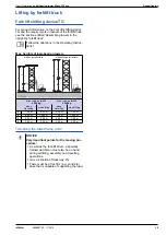
Page 39: ...rating Instruc tions with superstructure without superstructure Max load on forklift 4000 kg Max load on forklift 2000 kg when travelling when lifting when travelling when lifting a 7 20 m 9 00 m 5 00 m 7 00 m b 9 00 m 12 60 m 7 00 m 10 00 m c 5 40 m 9 00 m 4 00 m 7 00 m d 3 60 m 3 60 m 3 00 m 3 00 m NOTICE Very important points for the moving pro cedure As well as the fork lift driver a specially...

Page 40: ...CE In principle the system frames of the Load bearing towers Staxo 100 eco and Staxo 100 are compatible with one another Ideally how ever the tower frames should be assembled from components of the same system For details regarding structural design set up and use see the Doka Load bearing tower Staxo 100 User Information booklet ...

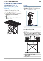
Page 41: ... onto the Screw jack foot Spanner size width across 24 mm Attaching the Dokamatic table Place the Dokamatic table onto the Staxo unit with the aid of two Dokamatic lifting straps 13 00m and the crane Fit Connecting pins 10cm to connect the table and secure these with spring cotters The second con necting pin on each longitudinal connection prevents any displacement of the table superstructure NOTI...

Page 42: ...e Screw jack foot If any more holes are needed in the Wedge for screw jack these can be drilled on site Details of extra holes in the Wedge for screw jack a 55 mm H Wedge for screw jack J Holes to be drilled diam 20 mm K Ready drilled hole diam 20 mm NOTICE Max table inclination 12 in both the longitu dinal and transverse directions 98026 214 01 H H 98026 215 01 a a J J K ...

Page 43: ... stair tower 12 kN in all directions Applies when fastened with Cone screw B 7cm and Universal climbing cone 15 0 or two dowels Required load bearing capacity of the dowels used Tensile force Rd 23 1 kN Fperm 14 0 kN Shear force Rd 6 6 kN Fperm 4 0 kN e g Hilti HST M16 in uncracked B30 concrete or equivalent products from other manufacturers Follow the manufacturer s applicable fitting instruction...

Page 44: ...joins NOTICE The load bearing tower must be stiffened with a diagonal cross in the anchoring plane H Diagonal cross NOTICE The actual design of the anchoring planes and the maximum permitted distances from the structure must be reviewed separately for each project Adjacent load bearing towers must be braced to one another as statically required in a similar way to when towers are anchored to the s...

Page 45: ...al force H R Resulting anchor force Z Anchor tensile force NOTICE Lashing straps are not suitable for transferring planned horizontal loads A Screw jack unit B Shoe complete x y z X C C B A Tr845 203 02 a b b b c a A B B Load bearing tower C Bracing for load bearing towers D Multi purpose waling E Connecting pin 10cm F Spring cotter 5mm X Tie rod 15 0 not included in scope of supply Length a minus...

Page 46: ...g force kN Anchor force kN Zk Qk Hk Rk Zd Qd Hd Rd α 30 a 18 2 26 0 31 7 27 3 39 0 47 6 α 45 a 27 6 21 2 34 8 41 4 31 8 52 2 α 60 a 44 8 15 0 47 2 67 2 22 5 70 8 Anchor force kN Zk Qk Hk Rk Zd Qd Hd Rd α 30 a 24 3 34 6 42 3 36 5 51 9 63 5 α 45 a 36 8 28 3 46 4 55 2 42 5 69 6 α 60 c 59 7 20 0 62 9 89 6 30 0 94 4 Anchor force kN Zk Qk Hk Rk Zd Qd Hd Rd α 30 b 30 4 43 3 52 9 45 6 65 0 79 4 α 45 b 46 ...

Page 47: ... waling directly by means of a spindle unit without a Shoe complete Permitted bracing force kN Bracing waling connector WS10 A Bracing waling connector WS10 B Multi purpose waling WS10 Top50 2 25m C Tie rod 15 0mm galvanised m 98087 227 01 98087 227 02 A B B C D E C G G H H F C G D Super plate 15 0 E Bracing for load bearing towers without Shoe complete F Eye lug anchor 15 0 without tie rod G Conn...

Page 48: ...for site erection A Load bearing tower B Plumbing strut Eurex 60 550 C Plumbing strut shoe Eurex 60 EB D Prop head Eurex 60 Top50 Required load bearing capacity of the dowels used Rd 25 5 kN Rperm 17 kN in any direction when 2 dowels are used CAUTION The plumbing strut must not be dismounted until it is certain that there is sufficient stabil ity for the load bearing tower A V 98087 228 01 H A B D...

Page 49: ...r heights the prop can be length ened to 7 50 m or 11 0 m In this case allow for the reduction in capacity as shown in the diagram Meets DIBT German Institute for Construction Engineering approvals criteria Special aluminium profile tubes give the prop its low weight of only 47 0 kg Can be telescoped in 10 cm increments with contin uous fine adjustment All parts are captively integrated telescopic...

Page 50: ...ttached wherever needed Examples between prop and load bearing tower frame between two or more props to facilitate erection of the prop as a handle for workers to hold onto Position of outer tube Prop length m at bottom at top 5 5 61 8 67 0 5 4 65 0 70 9 5 3 68 5 74 9 5 2 72 1 78 6 5 1 76 0 83 5 5 0 80 3 88 6 4 9 84 0 88 9 4 8 88 9 4 7 4 6 4 5 4 4 4 3 4 2 4 1 4 0 3 9 3 8 3 7 3 6 3 5 at bottom at t...

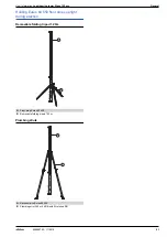
Page 51: ...019 Holding Eurex 60 550 floor props upright during erection Removable folding tripod 1 20m Plumbing struts A Floor prop Eurex 60 550 B Removable folding tripod 1 20m A Deckenstütze Eurex 60 550 B Plumbing strut 340 or 540 IB with Strut shoe EB 98003 315 01 A B 9703 256 01 A B ...

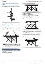
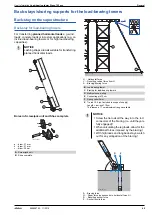
Page 52: ...afely transferred Note If the legs of the load bearing tower have to be located outside the pattern of drilled holes in the multi purpose waling then a suitable 20 mm diam hole must be drilled in the web of the waling using Staxo wedge support WU12 14 Same function as Staxo wedge support WS10 except that it is suitable for being pinned to a 12 cm or 14 cm high waling The wedge support is labelled ...

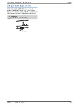
Page 53: ...2019 using an M20 hexagonal bolt In this case the superstructure rests on e g an M20x240 hexagonal bolt A This bolt is inserted through the recessed opening in the Screw jack U head and is secured with a self locking M20 hexagon nut CAUTION Maximum inclination 8 9716 292 01 A ...

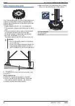
Page 54: ...aseplate 15 x 15 cm meaning that Eurex 60 550 cannot be stood on it α max angle 16 hs screw jack extension length determines design load of load bearing tower Set up instructions Place the Compensating plates on concrete Set the required angle with the black rotary plate The numbers must correspond see close up Position the Doka load bearing tower Make sure that the Compensating plate is sitting f...

Page 55: ...section girders Doka series walings Width x height mm Unsecured Max width 165 mm Secured centrally necessary from 12 Max width 165 mm Multi purpose waling WS10 Top50 153 x 100 Yes Yes Multi purpose waling WU12 Top50 163 x 120 Yes Yes Facade waling WU14 172 x 140 Yes 1 Yes 1 Multi purpose waling SL 1 WU16 183 x 160 Yes 1 Yes 1 System beam SL 1 226 x 240 No No Tr777 200 01 Tr777 201 01 Tr770 201 03 ...

Page 56: ...strap them together firmly h 220 cm Stack the frames at an offset to one another Utilise the benefits of Doka multi trip packaging on your site Multi trip packaging such as containers stacking pal lets and skeleton transport boxes keep everything in place on the site minimise time wasted searching for parts and streamline the storage and transport of sys tem components small items and accessories ...

Page 57: ...ruck The forks can be inserted under either the broadside or the narrowside of the containers Max load bearing capacity 700 kg 1540 lbs Permitted imposed load 3150 kg 6950 lbs Outdoors on the site Indoors Floor gradients up to 3 Floor gradients up to 1 2 5 It is not allowed to stack empty pallets on top of one another NOTICE Stacked multi trip boxes or pallets must have the heaviest boxes at the b...

Page 58: ...city 1500 kg 3300 lbs Permitted imposed load 7850 kg 17300 lbs A Slide bolt for fixing the partition Multi trip transport box partition in the longitudinal direction in the transverse direction 1 20m max 3 partitions 0 80m max 3 partitions 9206 204 01 A 9206 204 02 9206 204 03 Max carrying capacity 750 kg 1650 lbs Permitted imposed load 7200 kg 15870 lbs Outdoors on the site Indoors Floor gradient...

Page 59: ...i trip boxes or pallets must have the heaviest boxes at the bottom and the lightest at the top How to use with Bolt on castor set B Always apply the fixing brake when the container is parked When Doka stacking pallets are stacked the bottom pallet must NOT be one with a bolt on caster set mounted to it NOTICE Multi trip packaging items may only be lifted one at a time Use a suitable crane suspensi...

Page 60: ...ka accessory box Doka stacking pallets Max carrying capacity 1000 kg 2200 lbs Permitted imposed load 5530 kg 12191 lbs Outdoors on the site Indoors Floor gradients up to 3 Floor gradients up to 1 3 6 It is not allowed to stack empty pallets on top of one another NOTICE Stacked multi trip boxes or pallets must have the heaviest boxes at the bottom and the lightest at the top How to use with Bolt on...

Page 61: ...bearing plate for Screw jack U head Screw jack U head not restrained Inclination adjusted with a wooden wedge or Com pensating plate no effect on the restraint situation e g with Wedge for screw jack U head or Staxo wedge support Founding with the Compensating plate Ranges of use for top held systems Ranges of use for free standing systems For each 1 angle of inclination increase the minimum impos...

Page 62: ... 5 13 2 56 1 up to 1 20 30 45 1 0 3 7 8 83 1 5 15 75 1 0 6 5 7 8 77 1 8 15 65 1 Frame size m Screw jack extension lengths cm at top and bottom respectively Inter frame space m Number of frame planes connected to one another by diago nal crosses multi plane tower Max height m of load bearing tower without intermediate anchoring Intermediate anchor ing planes may be necessary while the towers are be...

Page 63: ...User Information Load bearing tower Staxo 100 eco Structural design 63 999808702 11 2019 ...

Page 64: ... 582335000 Diagonal cross 12 200 6 9 582614000 Diagonal cross 12 250 8 3 582616000 Diagonal cross 12 300 9 3 582325000 Diagonal cross 18 100 6 1 582620000 Diagonal cross 18 150 6 9 582622000 Diagonal cross 18 165 7 3 582629000 Diagonal cross 18 175 7 8 582336000 Diagonal cross 18 200 7 8 582624000 Diagonal cross 18 250 9 1 582626000 Diagonal cross 18 300 10 3 582326000 Diagonalkreuz U head D 6 7 5...

Page 65: ... floor prop Eurex 60 550 47 0 582650000 Doka Deckenstütze Eurex 60 550 Extension Eurex 60 2 00m 21 3 582651000 Verlängerung Eurex 60 2 00m Coupler Eurex 60 8 6 582652000 Kupplungsstück Eurex 60 U head Eurex 60 2 9 582656000 Gabelkopf Eurex 60 4 way head Eurex 60 4 5 582655000 Vierwegkopf Eurex 60 Length 20 cm Width 16 cm Galvanised Height 26 cm Galvanised Height 6 cm Diameter 12 cm Width across 27...

Page 66: ... 340 IB EF Plumbing strut 540 IB 30 7 588697000 Justierstütze 540 IB Plumbing strut 540 IB EF 28 9 588250500 Justierstütze 540 IB EF Strut shoe EB 0 93 588946000 Strebenschuh EB Prop shoe EB 1 8 588245500 Stützenschuh EB Universal dismantling tool 3 7 582768000 Universal Lösewerkzeug Powder coated blue Aluminium Length 343 553 cm Galvanised Height 50 cm Galvanised Length 15 cm Width 15 cm Height 3...

Page 67: ...tube 48 3mm 0 50m 1 7 682026000 Scaffold tube 48 3mm 1 00m 3 6 682014000 Scaffold tube 48 3mm 1 50m 5 4 682015000 Scaffold tube 48 3mm 2 00m 7 2 682016000 Scaffold tube 48 3mm 2 50m 9 0 682017000 Scaffold tube 48 3mm 3 00m 10 8 682018000 Scaffold tube 48 3mm 3 50m 12 6 682019000 Scaffold tube 48 3mm 4 00m 14 4 682021000 Scaffold tube 48 3mm 4 50m 16 2 682022000 Scaffold tube 48 3mm 5 00m 18 0 6820...

Page 68: ...ing plate T 3 1 584371000 Spindellasche T Connecting pin 10cm 0 34 580201000 Verbindungsbolzen 10cm Spring cotter 5mm 0 03 580204000 Federvorstecker 5mm Lifting rod 15 0 1 9 586074000 Umsetzstab 15 0 Retaining plate 15 0 1 8 586073000 Jochplatte 15 0 Universal plug R20 25 0 003 588180000 Kombi Ankerstopfen R20 25 Winch 70 31 0 582779000 Zahnstangenwinde 70 Galvanised Width 19 cm Height 46 cm Width...

Page 69: ...rt box 1 70x0 80m 87 0 583012000 Doka Gitterbox 1 70x0 80m Doka multi trip transport box 1 20x0 80m 70 0 583011000 Doka Mehrwegcontainer 1 20x0 80m Multi trip transport box partition 0 80m 3 7 583018000 Multi trip transport box partition 1 20m 5 5 583017000 Mehrwegcontainer Unterteilung Painted blue Height 189 cm Follow the directions in the Opera ting Instructions Painted blue Length 37 cm Width ...

Page 70: ...306000 Assembly planking 60 150cm 12 0 582307000 Assembly planking 60 175cm 14 7 582332000 Assembly planking 60 200cm 17 5 582308000 Assembly planking 60 250cm 21 0 582309000 Assembly planking 60 300cm 24 8 582310000 Montagebelag Assembly planking 60 100cm with manhole 10 2 582311000 Assembly planking 60 150cm with manhole 13 8 582312000 Assembly planking 60 175cm with manhole 15 0 582333000 Assem...

Page 71: ...User Information Load bearing tower Staxo 100 eco Component overview 71 999808702 11 2019 ...

Page 72: ...nd distributing formwork technology for use in all fields of the construction sector With more than 160 sales and logistics facilities in over 70 countries the Doka Group has a highly efficient dis tribution network which ensures that equipment and technical support are provided swiftly and profession ally An enterprise forming part of the Umdasch Group the Doka Group employs a worldwide workforce...

Reviews: