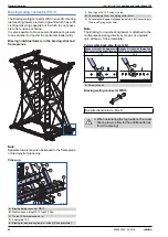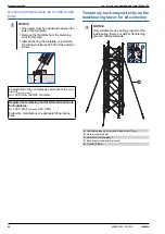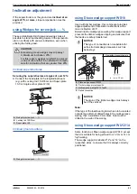
58
999804302 - 02/2018
General remarks
User Information
Load-bearing tower Staxo 100
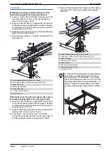
Back-stays/shoring supports for the load-bearing towers
Back-stay on the superstructure
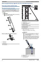
Back-stay for load-bearing towers
For transferring
planned horizontal loads
e.g. wind
loads, concrete loads or in custom applications (e.g. on
inclined load-bearing towers or for high load-bearing
capacities).
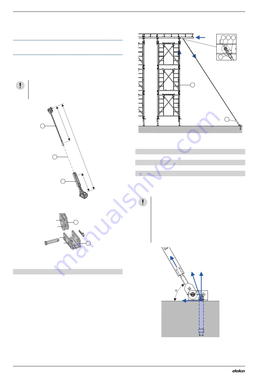
Bores in spindle unit and shoe (complete)
a ... dia. 21
mm
b ... dia. 27
mm
c ... Dia. 35
mm
H ... Horizontal force
V ... Resulting vertical force from H
A ... Back-stay/shoring force
A ... Back-stay force
Q ... Shear force (corresponds to horizontal force H)
R ... Resulting anchor force
Z ... Anchor tensile force
NOTICE
Lashing straps are
not
suitable for transferring
planned horizontal loads.
A
Screw-jack unit
B
Shoe complete
78.0
a
41.0
X
C
C
Tr845-203-02
a
b
b
b
c
a
A
B
B
Load-bearing tower
C
Bracing for load-bearing towers
D
Multi-purpose waling
E
Connecting pin 10cm
F
Spring cotter 5mm
X
Tie rod 15.0 (not included in scope of supply)
Length = a minus 119
cm
This leaves a 17
cm adjustment range available
NOTICE
▪
Screw the tie rods all the way in to the rod
connectors of the back-stay (i.e. until they
are fully engaged)!
▪
When calculating the leg loads, allow for the
additional forces imposed by the back-stay!
▪
With high loads and long back-stays, watch
out for any elongation of the back-stay!
H
A
V
98003-249-01
B
C
C
D E
F
A
R
Z
Q
9734-287-02

