12
999804302 - 02/2018
System description
User Information
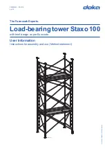
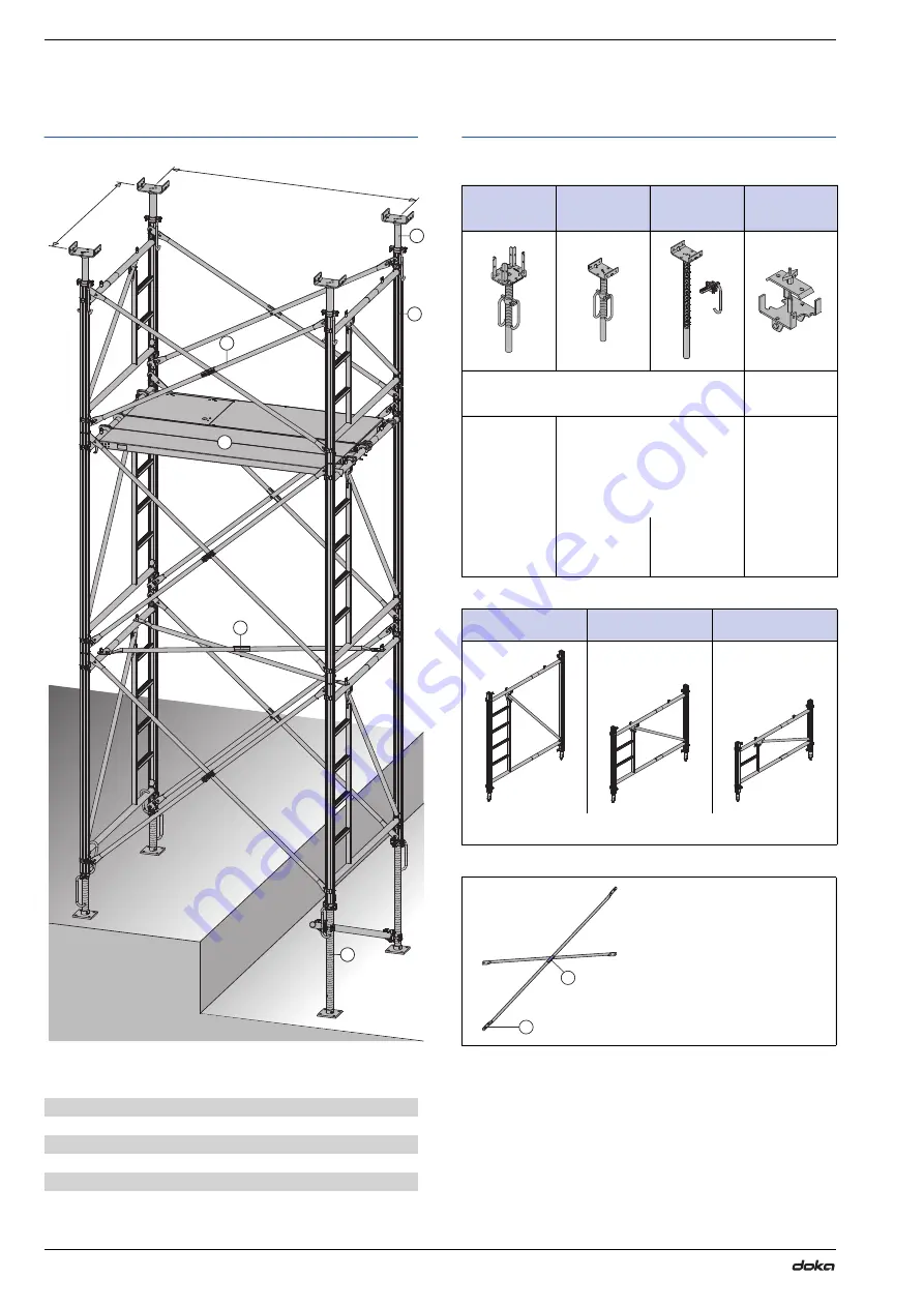
Load-bearing tower Staxo 100
System overview
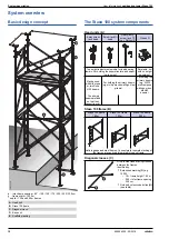
Basic design concept
a ... inter-frame spacing = 60* / 100 / 150 / 175 / 200 / 250 / 300
cm
b ... frame width = 152
cm
* only for 1.20 and 0.90m frames
The Staxo
100 system components
Head units (A)
Staxo
100 frame (B)
Diagonal crosses (C)
A
Head unit
B
Staxo
100 frame
C
Diagonal cross
D
Base unit
E
Scaffold planking
a
b
98003-228-01
B
A
C
E
D
C
4-way screw-
jack head
Screw jack U-
head
Heavy-duty
screw jack 70
top + Split nut B
U-head D
Top height-adjustment spindle for load-bearing
towers. For holding the superstructure and adjust-
ing its height.
Rotatable, but
with no height
adjustment.
May be used
with either one
or two Doka
H20 beams.
For holding the primary beams
(e.g. multi-purpose walings, steel
girders).
For holding the
primary beams
(e.g. WS10
multi-purpose
walings or dou-
ble H20
beams).
The primary
beams are fixed
so that they
cannot tip over.
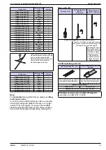
Staxo
100 frame
1.80m
Staxo
100 frame
1.20m
Staxo
100 frame
0.90m
Hot-dip galvanised steel frames. Connectors for upward stacking of
the frames are captively integrated into each frame.
Drop-in steel-tube bracing crosses
between the frames.
Identified by:
▪
Embossed marking
(G)
e.g.
18.250
- 18 = frame height 1.80
m
- 250 = inter-frame spacing
250
cm
▪
Notched, colour-coded clips
(H)
(see table)
G
H

