background image

50

999804302 - 02/2018 

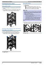
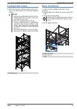
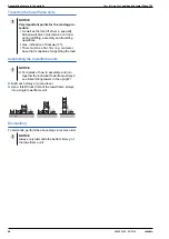
Repositioning

User Information 

Load-bearing tower Staxo 100

Repositioning

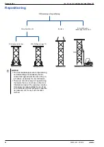
Different ways of repositioning

Using traveller units

By crane

By forklift truck or

telescoping stacker truck

With transport winches

 With Shifting carriage TG

98003-299-01

98003-300-01

98003-298-01

98003-296-01

NOTICE

 ▪

The most suitable approach to repositioning 

and dismantling should already be dis-

cussed and agreed with the site in the pro-

ject phase, especially for very tall towers.

 ▪

There are also other ways of repositioning 

the towers that are not shown in this User 

Information booklet. The customer (contrac-

tor) bears sole responsibility for use of all 

such methods and must prepare a separate 

risk assessment for any such intended 

method.

Summary of Contents for Staxo 100

Page 1: ...tetten 999804302 02 2018 en GB The Formwork Experts Load bearing tower Staxo 100 with brief design as per Eurocode User Information Instructions for assembly and use Method statement by Doka GmbH A 3300 Amstetten 98003 287 01 ...

Page 2: ...2 999804302 02 2018 User Information Load bearing tower Staxo 100 ...

Page 3: ...head railings 42 Assembling towers in the upright with mounted ahead 1 20m frames 47 Assembling towers in the upright by forklift truck 49 Practical examples 50 Repositioning 51 Repositioning using traveller units 53 Lifting by crane 55 Lifting by forklift truck 56 General remarks 56 Anchoring on the structure 58 Back stays shoring supports for the load bearing towers 63 Inclination adjustment 67 ...

Page 4: ... continually updating a hazard assessment at every job site This booklet serves as the basis for the site specific hazard assessment and for the instructions given to users on how to prepare and utilise the system It does not substitute for these however Remarks on this booklet This booklet can also be used as a generic method statement or incorporated with a site specific method statement Many of...

Page 5: ...to weld Doka products in par ticular anchoring tying components suspension components connector components and castings etc or otherwise subject them to heating Welding causes serious change in the microstruc ture of the materials from which these components are made This leads to a dramatic drop in the failure load representing a very great risk to safety It is permissible to cut tie rods to leng...

Page 6: ...an differ depending on material toler ances Dirt accretions moisture saturation etc can also affect weight We reserve the right to make alterations in the interests of technical progress Symbols used The following symbols are used in this document DANGER This is a notifier drawing attention to an extremely dangerous situation in which non compliance with this notifier will lead to death or severe ...

Page 7: ... Fd Design value of an action Steel Rd Rk Timber Rd kmod Rk Fd γF Fk γM γM F force Fk Characteristic value of an action actual load service load k characteristic e g dead weight live load concrete pressure wind Rk Characteristic value of the resistance e g moment resistance to yield stress γF Partial factor for actions in terms of load F force e g for dead weight live load concrete pres sure wind ...

Page 8: ... Stage Operations Scheduling Stage Taking well founded decisions thanks to professional advice and consulting Optimising the preliminary work with Doka as an experienced part ner Controlled regular forming oper ations for greater efficiency resulting from realistically calculated formwork concepts Find precisely the right formwork solutions with the aid of help with the bid invitation in depth ana...

Page 9: ...s are completely transparent there is no need for improvisation dur ing the project and no unpleas ant surprises at the end of it Reduced close out costs Our professional advice on the selection quality and correct use of the equipment helps you avoid damage and minimise wear and tear Concrete Construction Stage Project Close out Stage Optimum resource utilisation with assistance from the Doka For...

Page 10: ...l number of system components makes for easier handling and means that no time is wasted searching for parts the connector components are captively integrated into the frames and so cannot be lost no tools are needed for assembling the towers provides optimum safety high stability due to its 1 52 m wide frames slip proof ladders integrated in the frames suspension points for chest harness is flexi...

Page 11: ...ld e g for administra tion buildings and multistorey car park decks where large area tableform units reduce forming times in the industrial and power station construction field as a load bearing tower for all manner of applications Doka stair tower 250 The Doka stair tower 250 consists of 1 20 m frames and a small number of light weight aluminium stairway ele ments Quick to erect the stair tower p...

Page 12: ...earing towers For holding the superstructure and adjust ing its height Rotatable but with no height adjustment May be used with either one or two Doka H20 beams For holding the primary beams e g multi purpose walings steel girders For holding the primary beams e g WS10 multi purpose walings or dou ble H20 beams The primary beams are fixed so that they cannot tip over Staxo 100 frame 1 80m Staxo 10...

Page 13: ... Orange 3 These function in the same way as standard diagonal crosses but also have a permanently mounted waist level guardrail strut F This strut can also be retro fitted to standard diagonal crosses Designation Colour coded clip Notches Diagonal cross H 9 100 Green Diagonal cross H 9 150 Red Diagonal cross H 9 200 Blue Diagonal cross H 9 250 Yellow Diagonal cross H 12 100 Green 1 Diagonal cross ...

Page 14: ...amped in type designation 18 12 or 9 C Arrow to make clear where top and bottom are arrow pointing up frame is in correct position D Attachment point for personal fall arrest set D C B A 98003 206 01 WARNING Make sure that the anchorage point is at or above the required minimum height as oth erwise there will not be sufficient room to arrest a fall Attachment point allowed for personal fall arrest...

Page 15: ...defined positions closed open Connecting the couplers a max 16 cm exception where tubes are being connected for constructional design purposes b Diameter 48 mm c Diameter 75 mm Profile form low weight yet high load bearing capacity sturdy Yellow locking spring pushed toward the outside connection sleeve fixed Blue locking spring pushed toward the outside frames linked in crane handling safe manner...

Page 16: ...or nuts Vertical access system integral ladder extra handles to pick the frame up by WARNING Never climb up or down the outside of the tower You risk falling and or causing the tower to tip over Only ever climb up the inside of the tower When doing this make sure that the scaffold planking units are in the correct positions as intermediate landings 98003 255 01 98003 257 01 98003 257 01 ...

Page 17: ...acity of up to 97 kN per leg Staxo 100 is an extremely strong load bearing tower system It safely withstands horizontal forces such as wind loads The wide frames make for high stability right from the word go Close inter frame spacing is possible for transferring high loads A Load bearing tower B Dokaflex C Beam forming support 20 D Handrail post T 1 80m optionally with Toeboard holder T 1 80m Edg...

Page 18: ...ts and industrial structures the load bearing tower and Doka large area formwork Top 50 together make an ideal combination In this way even complex structures can be formed using mostly standard parts at lower cost Falsework beneath arched bridge Typical cross section Falsework beneath super structure formwork 9716 222 01 98003 232 01 ...

Page 19: ... of frame enable the frames to be spaced close together or further apart depending on the load In this way only as much material is used as is really needed e g light loads frames spaced further apart e g heavy loads frames spaced close together Plan view Plan view e g adapting to irregular shaped layouts by using single legs 98003 311 01 98003 309 01 9716 263 01 98003 310 01 98003 268 01 98003 26...

Page 20: ...0 frame 0 90m Staxo 100 frame 1 20m Staxo 100 frame 1 80m Diagonal cross 9 xxx Diagonal cross 12 xxx Diagonal cross 18 xxx h m min max h m min max h m min max 1 20 1 75 1 80 4 4 2 06 2 35 4 4 2 78 2 95 4 4 2 1 2 1 80 2 02 2 40 4 4 2 06 2 95 4 4 2 78 3 55 4 4 2 1 2 1 80 2 20 2 40 4 4 2 52 2 95 4 4 4 4 4 5 2 10 2 32 2 70 4 4 2 52 3 25 4 4 3 24 3 85 4 4 2 2 3 2 2 40 2 62 3 00 4 4 2 82 3 55 4 4 3 54 4...

Page 21: ...ty screw jacks 70 top However when these are combined with the small frames you must observe the limitations given in Tables B and C of the section headed Height adjustment Fixed height of frame F h m LK max 30 cm LF max 30 cm Basic items 4 way screw jack head or Screw jack U head Screw jack foot Staxo 100 frame 0 90m Staxo 100 frame 1 20m Diagonal cross 9 xxx Diagonal cross 12 xxx h m min max 1 2...

Page 22: ... Greater extension lengths are possible up to max 40 cm if the head units and or base units are given suitable scaffold tube brac ing In principle it is possible to use Heavy duty screw jacks 70 and Heavy duty screw jacks 70 top However when these are combined with the small frames you must observe the limitations given in Tables B and C of the section headed Height adjustment 98003 221 01 h h F h...

Page 23: ...th no formwork striking play NOTICE The structural design of the load bearing tower may make it necessary to plan for shorter extension lengths See the section headed Structural design for dimensioning details Screw jack U head and 4 way screw jack head Heavy duty screw jack 70 top U head D Frames in the top storey 1 80 1 20 0 90m 1 80m 1 20m 0 90m 1 80 1 20 0 90m LK max 45 8 71 2 71 2 71 2 1 6 LK...

Page 24: ...he screwjack head and base units and the integrated connector in the frame add up to a larger dimension than the height of the frame These constraint points have already been allowed for in the operational height data given in Table A Close up Cut away view of frame tube a b c Connector 30 5 Screw jack foot 69 2 Heavy duty screw jack 70 101 2 Heavy duty screw jack 130 173 0 Screw jack U head 68 8 ...

Page 25: ...ept the same distance apart Close up showing how the Staxo 100 planking strut is fixed to the Staxo 100 frame joint to make a deck ing level Width across 22 mm Note There is a height mismatch between the scaffold plank ing units placed on Staxo 100 planking struts and those placed on the Staxo 100 frames a 16 cm b 152 4 cm c1 97 6 cm with Staxo 100 planking strut 1 00m c2 147 6 cm with Staxo 100 p...

Page 26: ...he bracing strut plane guard rails may be erected using scaffold tubes 48 3mm and Transition swivel cou plers 48 76mm Tr827 202 04 B D Tr827 204 02 A C Tr827 205 02 C B Tr827 203 02 C D B A Staxo 100 planking strut 1 00m B Staxo 100 planking strut 1 50m C Scaffold planking D Diagonal cross where statically required E Scaffold tube 48 3mm F Transition swivel coupler 48 76mm Tr827 206 02 B Tr827 206...

Page 27: ...apter B Screw jack U head C Staxo 100 frame D Multi purpose waling WU12 Top50 E 4 way screw jack head F Bracing 98003 332 02 A A A A 98003 332 01 A D C E B F NOTICE It must be ensured in every single case that the screwjack U heads are restrained in both directions This may be achieved by way of contact to the structure nailed down floor slab formwork bracing Non restrained screw jack heads are no...

Page 28: ...28 999804302 02 2018 System description User Information Load bearing tower Staxo 100 Next fit on a 4 way screw jack head A Staxo 100 spindle adapter E 4 way screw jack head TR1009 203 02 A E ...

Page 29: ...ly overview Set up configurations Load bearing tower Staxo 100 Horizontal assembly Standard set up Assembling in the upright with Fork lift shifting device TG by hand Mounted ahead railings Mounted ahead 1 20m frames and diagonals 98003 213 01 98003 211 01 98003 101 98003 293 01 98003 294 01 ...

Page 30: ...the scaffold erector when erecting modifying or dismantling the load bear ing tower it may be necessary to use a personal fall arrest system mounted ahead frames and or railings or a combination of both NOTICE Use only the anchorage points as shown in the section headed The Staxo 100 frame in detail WARNING Make sure that the anchorage point is at or above the required minimum height as oth erwise...

Page 31: ...gard to the instructions given above place the tower frames on their sides on timber supports min 4cm high Bracing the frames in the vertical Link the frames with diagonal crosses NOTICE General remarks Slide the diagonal cross onto the safety catch bolt and immediately secure it with the safety catch 98003 206 01 98003 216 02 NOTICE When erecting the tower make sure that the climbing rungs are in...

Page 32: ... frame onto the finished section and push the blue locking spring of the bottom frame outward to join the frames Fit and secure diagonal crosses in the same way as in the first storey h max 10 m Install scaffold planking units where needed Basic rule Maintaining correct geometry by fixing a horizontal diagonal cross in the 1st and last but one or last storey and every 10 m Additionally as required...

Page 33: ...ed ahead railings Mount the Staxo side railings and secure them with a Spring locked connecting pin 16mm to prevent accidental lift out Close up 1 Mount Staxo front railings and secure them with a Spring cotter 5mm to prevent accidental lift out Close ups 2 and 3 Having scaffold planking units in the top sto rey makes it easier to carry out assembly work on the towerframe superstructure Determinin...

Page 34: ... tower is standing in the upright check once again to make sure that all the safety catches are closed 98003 214 01 Detaching the crane suspension tackle near ground level This method must not be used for placing the tower back on its side Items needed 3 x Scaffolding tube 48 3mm G Minimum length Inter frame space 1 00 m 6 x normal or swivel couplers 48mm H Attach scaffold tubes one between the bo...

Page 35: ...fety catch bolt and immediately secure it with the safety catch Example with Heavy duty screw jack 70 and 4 way screw jack head NOTICE Erect the load bearing tower in the vertical on ground that is statically capable of sup porting the load If the load bearing tower is over 6 m high back stay it or combine it with other towers 98003 206 01 98003 233 01 NOTICE When erecting the tower make sure that...

Page 36: ...k the frames with diagonal crosses Erecting the second storey Fitting the mounted ahead railings Mount Staxo side railings above the diagonal crosses Close up of how to hang into place Mount Staxo front railings above the Staxo 100 frames Close up of how to hang into place Make sure that the spring locking pin points downwards when it is secured A Split nut B B Heavy duty screw jack 70 C Spring lo...

Page 37: ...100 mounting gallows 40kg makes it easier to put up and take down Doka load bearing towers Staxo 100 when these are erected and dismantled in the upright Practical example G Scaffold planking G 98003 209 01 Tr842 200 01 Follow the directions in the Staxo 100 mount ing gallows 40kg Operating Instructions Permitted load bearing capacity 40 kg Staxo 100 mounting gallows 40kg Staxo 100 attaching cable...

Page 38: ... in the first storey Erecting the third storey Raising the mounted ahead railings 1 Push the Staxo front railings down into the stand by position 2 Move the Staxo side railings up one section sto rey 3 Move the Staxo front railings up again Mount the assembly planking Climb up onto the scaffold planking Fix on the frames in the same way as on the 2nd sec tion Yellow locking spring pushed toward th...

Page 39: ... place on all levels storeys with scaf fold planking units NOTICE If no scaffold planking units are used or if these are removed before the tower is finally put into use the following rule applies Basic rule Maintaining correct geometry by fixing a horizontal diagonal cross in the 1st and last but one or last storey and every 10 m Additionally as required e g if there is a horizontal restraint for...

Page 40: ... Blue locking spring J Head unit 98003 212 02 I J 9716 215 01 WARNING Where formwork beams cantilever out a long way secure them against accidental lift out WARNING Loads that are applied non centrally can cause overloading of the system Ensure that all loads are applied centrally NOTICE When lifting and repositioning the entire tower unit or pre assembled sub units by crane Follow the instruction...

Page 41: ...User Information Load bearing tower Staxo 100 Assembling towers in the upright 41 999804302 02 2018 ...

Page 42: ...ves together and secure it with the spring locking pin Press the yellow locking springs on the frame inwards to open the connection sleeves can now be moved freely Insert the Heavy duty screw jacks 70 into the frames Link the frames with diagonal crosses NOTICE Erect the load bearing tower in the vertical on ground that is statically capable of sup porting the load If the load bearing tower is ove...

Page 43: ...utward to join the frames Push diagonal crosses onto the bottom safety catch bolts and secure them with the safety catches Bracing the frames in the vertical Raise the scaffold planking units to the next level Push diagonal crosses onto the top safety catch bolts and secure them with the safety catches G Scaffold planking G 98003 273 01 Tr842 200 01 98003 262 01 Yellow locking spring pushed toward...

Page 44: ...crosses onto the safety catch bolts of the horizontal frame tubes and fix them in place G Scaffold planking F Diagonal cross 98003 264 01 F G 98003 261 01 NOTICE If no scaffold planking units are used or if these are removed before the tower is finally put into use the following rule applies Basic rule Maintaining correct geometry by fixing a horizontal diagonal cross in the 1st and last but one o...

Page 45: ...CE Arrange the scaffold planking units either on alternate sides from one storey to the next or across the entire area When the scaffold planking units are located on alternate sides 3 scaffold plank ing units must be used on the final i e top storey one of them with a manhole Make sure that the manhole is in the correct posi tion here If the load bearing tower is over 6 m high back stay it or com...

Page 46: ... Blue locking spring J Head unit 98003 212 02 I J 9716 215 01 WARNING Where formwork beams cantilever out a long way secure them against accidental lift out WARNING Loads that are applied non centrally can cause overloading of the system Ensure that all loads are applied centrally NOTICE When lifting and repositioning the entire tower unit or pre assembled sub units by crane Follow the instruction...

Page 47: ... Screw on coupler 48mm 50 4 G Scaffold tube 48 3mm 2 00m 1 H Swivel coupler 48mm 2 Operating cord site provided optional 1 WARNING While load bearing towers are being erected or dismantled lifted or lowered It is forbid den to walk or stand beneath suspended loads Max load on forklift Max load on Fork lift shifting device with box style fork extensions with telescopic forks 4000 kg 1000 kg 600 kg ...

Page 48: ... in reverse order NOTICE Very important points for the moving pro cedure As well as the fork lift driver a specially trained watchman must also be on hand during all lifting assembly and travelling operations max inclination of trackway 2 There must be a flat firm e g concrete base that is capable of supporting the load NOTICE For details of how to assemble and join together the individual towerfr...

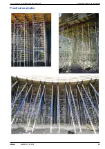
Page 49: ...User Information Load bearing tower Staxo 100 Assembling towers in the upright 49 999804302 02 2018 Practical examples ...

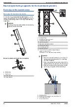
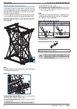
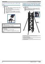
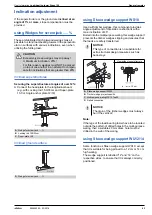
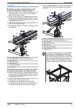
Page 50: ...8003 300 01 98003 298 01 98003 296 01 NOTICE The most suitable approach to repositioning and dismantling should already be dis cussed and agreed with the site in the pro ject phase especially for very tall towers There are also other ways of repositioning the towers that are not shown in this User Information booklet The customer contrac tor bears sole responsibility for use of all such methods an...

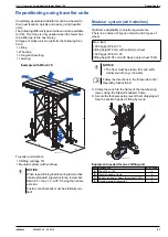
Page 51: ... of wheel Clamp the winch to the frame of the load bearing tower using the Staxo d2 adapter frame Secure the foot pieces to prevent them dropping out See the section headed Lifting by crane Equipment needed for one shifting unit NOTICE When repositioning load bearing towers that include standard superstructures remember Ratio b h max 1 3 with b being the narrow est side Custom constructions must b...

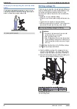
Page 52: ...dth of only 82 cm the carriage can pass easily through any doorway when empty Push the Shifting carriage TG up against the nar rowsides of the tableform the slot in lifting profile reaches under the bottom cross tube of the frame Secure the foot pieces to prevent them dropping out See the section headed Lifting by crane Equipment needed for one shifting unit A Double wheeled transporter 9716 220 0...

Page 53: ...dle into the cross tube of the frame Secure the base units to prevent them dropping out Slot the fixing handle into the cross tube of the frame NOTICE The max height of towerframe unit that can be lifted in one piece is 20 m Max load 1000 kg per Lifting rod 15 0 where the load is applied centrally A Lifting rod 15 0 B Retaining plate 15 0 Use a 20 mm diam bit to drill the hole through the form ply...

Page 54: ...e stop Remove the front wheel units Screw the Lifting rod 15 0 into the previously mounted Retaining plate 15 0 Attach the crane sling to the Lifting rod 15 0 then raise the crane until the front legs are just off the floor Push the table outwards until only the innermost legs are still over the floor Mount more lifting rods and attach crane slings Use a chain hoist to shorten the rear cables unti...

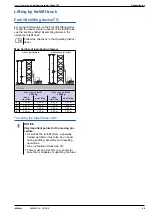
Page 55: ...ting Instruc tions with superstructure without superstructure Max load on forklift 4000 kg Max load on forklift 2000 kg when travelling when lifting when travelling when lifting a 7 20 m 9 00 m 5 00 m 7 00 m b 9 00 m 12 60 m 7 00 m 10 00 m c 5 40 m 9 00 m 4 00 m 7 00 m d 3 60 m 3 60 m 3 00 m 3 00 m NOTICE Very important points for the moving pro cedure As well as the fork lift driver a specially t...

Page 56: ...kN Anchorage method Max anchoring loads kN per anchor Concrete strength at the time of loading Tensile force Z Shear force Q Tensile force Z Shear force Q 6 0 6 0 1 dowel in the centre hole 14 0 6 0 fck cube current 20 N mm2 12 0 6 0 2 dowels one in each of the outer holes e g Doka express anchor 16x125mm 13 3 3 0 fck cube current 15 N mm2 1 Cone screw B 7cm in the centre hole 44 0 6 0 fck cube cu...

Page 57: ...ractical example NOTICE The load bearing tower must be stiffened with a diagonal cross in the anchoring plane H Diagonal cross NOTICE The actual design of the anchoring planes and the maximum permitted distances from the structure must be reviewed separately for each project Adjacent load bearing towers must be braced to one another as statically required in a similar way to when towers are anchor...

Page 58: ...force H R Resulting anchor force Z Anchor tensile force NOTICE Lashing straps are not suitable for transferring planned horizontal loads A Screw jack unit B Shoe complete 7 8 0 a 4 1 0 X C C Tr845 203 02 a b b b c a A B B Load bearing tower C Bracing for load bearing towers D Multi purpose waling E Connecting pin 10cm F Spring cotter 5mm X Tie rod 15 0 not included in scope of supply Length a minu...

Page 59: ...k Hk Rk Zd Qd Hd Rd α 30 a 18 2 26 0 31 7 27 3 39 0 47 6 α 45 a 27 6 21 2 34 8 41 4 31 8 52 2 α 60 b 44 8 15 0 47 2 67 2 22 5 70 8 Anchor force kN Zk Qk Hk Rk Zd Qd Hd Rd α 30 a 24 3 34 6 42 3 36 5 51 9 63 5 α 45 b 36 8 28 3 46 4 55 2 42 5 69 6 α 60 c 59 7 20 0 62 9 89 6 30 0 94 4 Anchor force kN Zk Qk Hk Rk Zd Qd Hd Rd α 30 b 30 4 43 3 52 9 45 6 65 0 79 4 α 45 c 46 0 35 4 58 0 69 0 53 1 87 0 α 60...

Page 60: ... waling directly by means of a spindle unit without a Shoe complete Permissible back stay force kN Bracing waling connector WS10 A Bracing waling connector WS10 B Multi purpose waling WS10 Top50 2 25m C Tie rod 15 0mm galvanised m D Super plate 15 0 E Bracing for load bearing towers without Shoe complete Tr845 200 01 Tr845 200 03 A B B C D E C C G G H H F G F Eye lug anchor 15 0 without tie rod G ...

Page 61: ... Doka express anchors Anchoring the footplate The Doka express anchor can be re used many times over Anchored with one dowel up to 15 kN tensile force CAUTION Do not remove the compression bracing before adequate stability for the load bear ing tower is ensured A Load bearing tower B Plumbing strut Eurex 60 550 C Plumbing strut shoe Eurex 60 EB D Prop head Eurex 60 Top50 Permitted load bearing cap...

Page 62: ...rex 60 550 at the position shown Characteristic cube compressive strength of the con crete fck cube current min 30 N mm2 C25 30 concrete Required safe working load of alternative anchors for footplates Rd 30 0 kN Fpermissible 20 0 kN Follow the manufacturers applicable fitting instruc tions 9745 222 03 NOTICE Only suitable for use during erection of the load bearing tower but not for transferring ...

Page 63: ...fely transferred Note If the legs of the load bearing tower have to be located outside the pattern of drilled holes in the multi purpose waling then a suitable 20 mm diam hole must be drilled in the web of the waling using Staxo wedge support WU12 14 Same function as Staxo wedge support WS10 except that it is suitable for being pinned to a 12 cm or 14 cm high waling The wedge support is labelled 1...

Page 64: ...design limitations must be taken into account Swivel bearing plate for Screw jack U head on head unit only Use only the permitted leg loads for Head units not restrained for construct ing the superstructure but do not exceed 65 kN Swivel bearing plate for Screw jack U head on both head and base unit Use only the permitted leg loads for Head units not restrained for construct ing the superstructure...

Page 65: ...ural steel section on the Swivel bearing plate for Screw jack U head From below insert Locking rods 15 0 330mm through the punched out holes on the bent edge of the Swivel bearing plate for Screw jack U head Place a Clamping plate for U head over the Locking rods 15 0 and screw it down tightly with hexagon nuts 15 0 A Swivel bearing plate for Screw jack U head B Screw jack U head or Heavy duty scr...

Page 66: ...baseplate 15 x 15 cm meaning that Eurex 60 550 cannot be stood on it α max angle 16 hs screw jack extension length determines design load of load bearing tower Set up instructions Place the Compensating plates on concrete Set the required angle with the black rotary plate The numbers must correspond see close up Position the Doka load bearing tower Make sure that the Compensating plate is sitting ...

Page 67: ...ll depend on the size of frame and the inter frame space F Diagonal cross 9 xxx where distance c is between 120 cm and 150 cm otherwise use a scaffolding tube as bracing WARNING Allow for the reduced loading capacities Can only be used on top held load bearing towers Allow for higher assumed wind loads NOTICE Horizontal diagonal crosses 9 xxx are needed at intervals of every two storeys beginning ...

Page 68: ...Adapting to angled or curved layouts Wheeling H Scaffold tube 48 3mm I Swivel coupler 48mm 98003 319 02 H I 98003 271 01 98003 268 01 98003 269 01 A Staxo 100 single leg 1 80 1 20 or 0 90 m B Scaffolding tube 48 3mm C Swivel coupler 48mm NOTICE Before a Staxo tower with extra legs can be wheeled vertical bracing must be added in the bottom storey between these single legs and the Staxo 100 tower C...

Page 69: ... prop can be length ened to 7 50 m or 11 0 m In this case allow for the reduction in capacity as shown in the diagram Meets DIBT German Institute for Construction Engineering approvals criteria Special aluminium profile tubes give the prop its low weight of only 47 0 kg Can be telescoped in 10 cm increments with contin uous fine adjustment All parts are captively integrated telescopic tube has ant...

Page 70: ... attached wherever needed Examples between prop and load bearing tower frame between two or more props to facilitate erection of the prop as a handle for workers to hold onto Position of outer tube Prop length m at bottom at top 5 5 61 8 67 0 5 4 65 0 70 9 5 3 68 5 74 9 5 2 72 1 78 6 5 1 76 0 83 5 5 0 80 3 88 6 4 9 84 0 88 9 4 8 88 9 4 7 4 6 4 5 4 4 4 3 4 2 4 1 4 0 3 9 3 8 3 7 3 6 3 5 at bottom at...

Page 71: ... 2018 Holding Eurex 60 550 floor props upright during erection Removable folding tripod 1 20m Plumbing struts A Floor prop Eurex 60 550 B Removable folding tripod 1 20m A Deckenstütze Eurex 60 550 B Plumbing strut 340 or 540 IB with Strut shoe EB 98003 315 01 A B 9703 256 01 A B ...

Page 72: ...econdary beam stabilisers 1 approx 10 Secondary beam stabilisers 2 Note In certain special situations e g when forming inclined floor slabs Secondary beam stabilisers can also be used for transferring horizontal loads For more information please contact your Doka techni cian Assembly Hang the Secondary beam stabilisers into place with an Alu beam fork H20 The secondary beam is now held in place La...

Page 73: ...a tion booklet and type test only apply to mono system tower frames If this is not possible then the following points must be remembered The lower leg loads permitted for the Staxo system must be assumed Custom applications with permitted capacities of 85 or 97 kN per leg are not possible No type test At the very least each storey must be assembled from components of the same system because the tw...

Page 74: ... onto the Screw jack foot Spanner size width across 24 mm Attaching the Dokamatic table Place the Dokamatic table onto the Staxo unit with the aid of two Dokamatic lifting straps 13 00m and the crane Fit Connecting pins 10cm to connect the table and secure these with spring cotters The second con necting pin on each longitudinal connection prevents any displacement of the table superstructure NOTI...

Page 75: ...the Screw jack foot If any more holes are needed in the Wedge for screw jack these can be drilled on site Details of extra holes in the Wedge for screw jack a 55 mm H Wedge for screw jack J Holes to be drilled diam 20 mm K Ready drilled hole diam 20 mm NOTICE Max table inclination 12 in both the longitu dinal and transverse directions 98026 214 01 H H 98026 215 01 a a J J K ...

Page 76: ...I section girders Doka series walings Width x height mm Unsecured Max width 165 mm Secured centrally necessary from 12 Max width 165 mm Multi purpose waling WS10 Top50 153 x 100 Yes Yes Multi purpose waling WU12 Top50 163 x 120 Yes Yes Facade waling WU14 172 x 140 Yes 1 Yes 1 Multi purpose waling SL 1 WU16 183 x 160 Yes 1 Yes 1 System beam SL 1 226 x 240 No No Tr777 200 01 Tr777 201 01 Tr770 201 0...

Page 77: ...t it into position Set the multi purpose waling on the coupler Clamp the Multi purpose waling WS10 to the cou pler Set the next Staxo 100 frame on the coupler and bolt it into position The scope of supply of the Coupler WS10 250 includes 2 hexagon bolts M16x80 2 hexagon bolts M16x160 4 washers 16 4 hexagon nuts M16 self locking Note As an alternative to the bolts it is also possible to establish t...

Page 78: ...s of Doka multi trip packaging on your site Multi trip packaging such as containers stacking pal lets and skeleton transport boxes keep everything in place on the site minimise time wasted searching for parts and streamline the storage and transport of sys tem components small items and accessories Max load bearing capacity 750 kg Permitted imposed load 1630 kg max 3 stacked pal lets NOTICE Multi ...

Page 79: ...axo Staxo 100 frame 1 20m 3 3 Staxo Staxo 100 frame 1 80m 2 3 NOTICE When empty pallets are stacked the lash ing straps must be wound around the verti cal profiles attached to the belt hook and tensioned Type of frame Max number of pallets Stacked on the site all 17 Stacking in the warehouse all 27 WARNING Do not attach the lifting chain to the Staxo or Aluxo frames The lashing strap is not design...

Page 80: ...llet stacking truck The forks can be inserted under either the broadside or the narrowside of the containers Max load 700 kg 1540 lbs Permitted imposed load 3150 kg 6950 lbs NOTICE Multi trip packaging items that each contain very different loads must be stacked with the heaviest ones at the bottom and the lightest ones at the top Rating plate must be in place and clearly legible Outdoors on the s...

Page 81: ...ks can be inserted under either the broadside or the narrowside of the containers Max load 1500 kg 3300 lbs Permitted imposed load 7850 kg 17305 lbs NOTICE Multi trip packaging items that each contain very different loads must be stacked with the heaviest ones at the bottom and the lightest ones at the top Rating plate must be in place and clearly legible A Slide bolt for fixing the partition Tr75...

Page 82: ...mitted imposed load 5900 kg 12980 lbs NOTICE Multi trip packaging items that each contain very different loads must be stacked with the heaviest ones at the bottom and the lightest ones at the top Rating plate must be in place and clearly legible Outdoors on the site Indoors Floor gradients of up to 3 Floor gradients of up to 1 2 6 It is not allowed to stack empty pallets on top of one another NOT...

Page 83: ...rrowside of the containers Bolt on castor set B The Bolt on caster set B turns the stacking pallet into a fast and manoeuvrable transport device Suitable for drive through access openings 90 cm The Bolt on caster set B can be mounted to the follow ing multi trip packaging items Doka accessory box Doka stacking pallets Max load 1000 kg 2200 lbs Permitted imposed load 5530 kg 12191 lbs NOTICE Multi ...

Page 84: ...tow away the loose connection sleeve so that it can be reinstalled in the Staxo 100 frame when work is finished Installation Use a screwdriver to press the spring out of the way Push the connection sleeve into the frame tube from below until it hits the stop make sure that the spring A is in the right position Use a screwdriver to press the rear stop out of the way Keep pushing in the connection s...

Page 85: ... head Screw jack U head not restrained Inclination adjusted with a wooden wedge or Com pensating plate no effect on the restraint situation e g with Wedge for screw jack U head or Staxo wedge support Founding with the Compensating plate Ranges of use for top held systems Ranges of use for free standing systems For each 1 angle of inclination increase the minimum imposed loads by 10 max 160 This fu...

Page 86: ...lane tower Max height m of load bearing tower without intermediate anchoring Intermediate anchor ing planes may be necessary while the towers are being erected Permitted leg load kN Unbraced Braced Head units restrained Head units not restrained up to 1 80 30 70 1 5 2 3 2 67 60 20 70 61 up to 1 20 30 45 1 5 2 2 1 89 20 94 1 0 3 2 1 87 21 93 0 6 5 2 1 87 21 91 up to 1 20 with 0 90 in topandbottom s...

Page 87: ...g D Swivel coupler 48mm F Split nut B T Heavy duty screw jack 70 V Heavy duty screw jack 70 top Y Extra bracing is only necessary if the screw jack heads are not connected with one another by way of the formwork base Z Scaffold tube 48 3mm 98003 288 01 V Y D Z Z D F Y 98003 288 02 Z T Z D D F ...

Page 88: ...9 1 582626000 Diagonal cross 18 300 10 3 582326000 Diagonalkreuz Diagonal cross H 9 100 5 7 582337000 Diagonal cross H 9 150 7 2 582338000 Diagonal cross H 9 200 9 3 582339000 Diagonal cross H 9 250 11 3 582340000 Diagonal cross H 12 100 5 8 582341000 Diagonal cross H 12 150 7 5 582342000 Diagonal cross H 12 200 9 3 582343000 Diagonal cross H 12 250 10 5 582344000 Diagonalkreuz H U head D 6 7 5827...

Page 89: ... 2 582239000 Ausgleichsplatte Staxo 100 single leg 0 90m 20 2 582305000 Staxo 100 single leg 1 20m 21 5 582304000 Staxo 100 single leg 1 80m 17 0 582303000 Staxo 100 Einzelstiel Doka floor prop Eurex 60 550 47 0 582650000 Doka Deckenstütze Eurex 60 550 Extension Eurex 60 2 00m 21 3 582651000 Verlängerung Eurex 60 2 00m Coupler Eurex 60 8 6 582652000 Kupplungsstück Eurex 60 Length 20 cm Width 16 cm...

Page 90: ...IB 16 7 588696000 Justierstütze 340 IB Plumbing strut 340 IB EF 14 9 588247500 Justierstütze 340 IB EF Plumbing strut 540 IB 30 7 588697000 Justierstütze 540 IB Plumbing strut 540 IB EF 28 9 588250500 Justierstütze 540 IB EF Strut shoe EB 0 93 588946000 Strebenschuh EB Galvanised Length 22 cm Width 20 cm Height 12 cm Galvanised Length 25 cm Width 21 cm Height 21 cm Powder coated blue Aluminium Len...

Page 91: ...Scaffold planking 60 100cm 9 5 582306500 Scaffold planking 60 150cm 13 6 582307500 Scaffold planking 60 175cm 15 5 582332500 Scaffold planking 60 200cm 17 8 582308500 Scaffold planking 60 250cm 22 2 582309500 Scaffold planking 60 300cm 26 2 582310500 Gerüstbelag Staxo 100 toeboard 5 5 582329000 Staxo 100 Fußwehr Staxo 100 planking strut 1 00m 6 1 582348000 Staxo 100 planking strut 1 50m 9 0 582349...

Page 92: ...cm 0 86 581444000 Konusschraube B 7cm Brace stirrup 8 2 7 582751000 Spannbügel 8 Rafter plate right 0 09 582521000 Rafter plate left 0 09 582522000 Sparrenpfettenanker Handrail post 1 50m 12 4 582754000 Geländer 1 50m Handrail clamp S 11 5 580470000 Schutzgeländerzwinge S Handrail post T 1 80m 17 7 584373000 Einschubgeländer T 1 80m Toeboard holder T 1 80m 0 53 584392000 Fußwehrhalter T 1 80m Scaf...

Page 93: ...e 15 0 1 8 586073000 Jochplatte 15 0 Universal plug R20 25 0 003 588180000 Kombi Ankerstopfen R20 25 Coupler WS10 250 6 9 582688000 Kupplungsstück WS10 250 Winch 70 31 0 582779000 Zahnstangenwinde 70 Winch 125 63 8 582780000 Zahnstangenwinde 125 Staxo d2 adapter frame 14 1 582781000 Staxo d2 Adapter Solid tire wheel 34 5 582573000 Vollelastikrad Galvanised Painted blue Galvanised Length 46 7 cm Ga...

Page 94: ...lti trip transport box partition 0 80m 3 7 583018000 Multi trip transport box partition 1 20m 5 5 583017000 Mehrwegcontainer Unterteilung Doka stacking pallet 1 55x0 85m 41 0 586151000 Doka Stapelpalette 1 55x0 85m Doka stacking pallet 1 20x0 80m 38 0 583016000 Doka Stapelpalette 1 20x0 80m Doka accessory box 106 4 583010000 Doka Kleinteilebox Painted blue Height 41 cm Painted blue Width 57 cm Gal...

Page 95: ...9804302 02 2018 User Information Load bearing tower Staxo 100 Component overview Bolt on castor set B 33 6 586168000 Anklemm Radsatz B Stacking strap 50 3 1 586156000 Stapelgurt 50 Painted blue Powder coated blue Packaging unit 2 pcs ...

Page 96: ...ting formwork technology for use in all fields of the construction sector With more than 160 sales and logistics facilities in over 70 countries the Doka Group has a highly efficient dis tribution network which ensures that equipment and technical support are provided swiftly and profession ally An enterprise forming part of the Umdasch Group the Doka Group employs a worldwide workforce of more th...

Reviews: