background image

3.1 Installing a bracket

You can install the DSR1090 using an industry-standard speaker bracket that is designed to support the
weight of the speaker and is in compliance with Section 2.4 in this manual or the optional YK1090 yoke or
MMA1090 multipoint. (See the link at the end of this section.) The rear panel has an industry-standard hole
pattern and will accept a variety of brackets for mounting and aiming.

About this task
This tool is required to install the bracket:
• 4 mm hex driver
Procedure
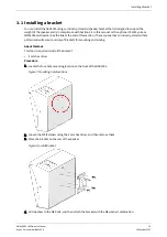
1. Locate the four-hole mounting location on the back of the DSR1090.

Figure 7: Mounting hole locations

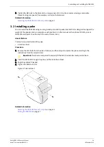
2. Loosen the M6 fasteners using the 4 mm hex driver, and then remove them.
3. Place the bracket on the rear of the speaker.

Figure 8: Install bracket

4. Add washers to the M6 bolts, and then attach the bracket with the M6 washer combination.

Installing a bracket

Dolby DSR1090 Owner's Manual

15

Issue 1 Part number: 8800304

16 October 2022

Summary of Contents for DSR1090

Page 1: ...Dolby DSR1090 Owner s Manual 16 October 2022 Issue 1 Part number 8800304 ...

Page 2: ...nced Audio Dolby Digital Plus Home Theater Dolby Home Theater Dolby Theatre Dolby Vision Dolby Vision IQ Dolby Voice Feel Every Dimension Feel Every Dimension in Dolby Feel Every Dimension in Dolby Atmos MLP Lossless Pro Logic Surround EX All other trademarks remain the property of their respective owners Product model THIS DOCUMENTATION APPLIES TO THE DOLBY DSR1090 SPEAKER MODEL CID1028 Limited w...

Page 3: ...imulations 12 2 7 Additional information 12 2 8 Contacting Dolby 12 3 Assembling and installing the DSR1090 14 3 1 Installing a bracket 15 3 2 Installing a yoke 16 3 3 Aiming the DSR1090 17 3 3 1 Using a laser for horizontal aiming 17 3 3 2 Using a laser for vertical aiming 17 3 4 Installing the safety cable 18 3 5 Connecting and configuring the DSR1090 19 4 Dolby DSR1090 specifications 21 4 1 Dol...

Page 4: ...al regulations Installers in other countries should consult with appropriate engineering and regulatory authorities for specific guidelines Any supplied rigging hardware is intended only for use with the specified speaker s The installer assumes all risk of loss and or injury arising out of the use of the supplied rigging hardware with any other speaker All other rigging is considered part of the ...

Page 5: ...e members Caution should be taken to avoid prolonged exposure to SPL in excess of 90 dB Caution Vibration from this type of speaker system may cause cabinets to shift Failure to secure the speaker cabinet to the building structure may result in the speaker system tipping or falling which may cause damage or injury Caution Make sure that no water pipes natural gas lines electrical wire or conduit a...

Page 6: ...product disposal information Restriction of Hazardous Substances Directive RoHS All Dolby products comply with the requirements of the EU RoHS Directive This product is electronic equipment and should be disposed of in accordance with all applicable laws Do not dispose as household waste Do not dispose of the product in a fire Please dispose of this product by taking it to your local electronic wa...

Page 7: ...oth transducers are finite element modeling FEM optimized which allows the transducers to deliver high sound pressure levels with minimal distortion These advanced drivers coupled with the Dolby industry leading system design and support philosophy allow for exceptional performance and quick easy installation and service Figure 1 Dolby DSR1090 Following is an outline of this chapter About this doc...

Page 8: ...e polymer dome with a frequency response up to 20 kHz The low frequency driver is a 10 inch transducer with a finite element modeling FEM optimized motor and suspension optimized cooling for low power compression and a high excursion rating An industry standard four hole mounting point on the rear of the enclosure allows for simplified and flexible mounting solutions Holes on the sides of the spea...

Page 9: ...tral listening area CLA For Dolby Atmos installations to determine the proper horizontal aiming for the side and rear surround speakers you need to define a rectangle within the CLA that includes the reference listening position RLP For side and rear surround speakers that are adjacent to the CLA aim the speakers directly into the auditorium that is 0 from perpendicular 10 For installations that u...

Page 10: ...Side and rear speakers vertical aiming 2 3 4 Determining the top surround position You must always place top surround speakers as left right pairs with the left speaker and right speaker located at the same distance from the front wall You must place the top surround speaker pairs symmetrically with respect to the screen center line Typically the top surround arrays are placed in line with the lef...

Page 11: ...ld separately YK1090 MMA1090 or you can purchase them from a party other than Dolby such as Adaptive Technologies or MN Mounting Solutions You should choose a mounting bracket or yoke that meets the mounting requirements of the auditorium allowing for the required vertical and horizontal angle adjustment The bracket or yoke must support the weight of the DSR1090 31 lb or 14 kg with at least a 5 1 ...

Page 12: ...rhead gll polar file references the zero degree vertical aiming reference to the front of the enclosure so that the transducers directly point to the aiming location in the gll file 2 7 Additional information There is additional information regarding the DSR1090 that you need to consider System weight for stability calculations is approximately 14 1 kg 31 lb Amplifier selection is aided by additio...

Page 13: ...entation Visit https customer dolby com Submit feedback about this documentation Send an email to documentation dolby com Contacting Dolby Dolby DSR1090 Owner s Manual 13 Issue 1 Part number 8800304 16 October 2022 ...
Page 14: ...mounting hardware supports and brackets not supplied by Dolby Any modification to the speaker system for example mounting by drilling holes into the speaker system will render the product warranty null and void Following is an outline of this chapter Installing a bracket Installing a yoke Aiming the DSR1090 Installing the safety cable Connecting and configuring the DSR1090 Assembling and installin...

Page 15: ...a variety of brackets for mounting and aiming About this task This tool is required to install the bracket 4 mm hex driver Procedure 1 Locate the four hole mounting location on the back of the DSR1090 Figure 7 Mounting hole locations 2 Loosen the M6 fasteners using the 4 mm hex driver and then remove them 3 Place the bracket on the rear of the speaker Figure 8 Install bracket 4 Add washers to the ...

Page 16: ...at the end of this section About this task This tool is required to install the yoke 6 mm hex driver Procedure 1 Remove the M10 bolts from the side of cabinet and then adjust and place the yoke according to the instructions from the manufacturer Important If washers are required to properly fit the bolt the installer must provide them 2 Insert the M10 bolts through the yoke and then into the cabin...

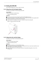
Page 17: ...SR1090 horizontally until the laser is directed at the specified aiming point Figure 10 Aiming the DSR1090 horizontally 3 3 2 Using a laser for vertical aiming Instructions are provided for vertical aiming using a laser About this task This tool is required for vertical aiming Installer provided laser pointer Procedure 1 Place the laser pointer on top of the DSR1090 enclosure 2 Align the laser lev...

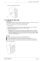
Page 18: ...hreaded shaft that is at least 20 mm long Based on the weight of the DSR1090 31 lb 14 kg all installer supplied safety rigging hardware must be rated at a minimum 5 1 safety factor or greater if a higher requirement is mandated per local laws Remove all slack to avoid any shock loading of the cable in the event of a primary rigging failure Procedure 1 Locate the safety eyebolt mounting location on...

Page 19: ...Per IEC standards a positive voltage on the positive marked input causes the transducers to move outward Procedure 1 Locate the input plate on the top of the DSR1090 2 Strip back the wire insulation sheath to 18 mm 3 Locate the spring loaded orange terminal tab on the input plate and then push it inward Pushing it inward opens the gap in the hole directly below the tab 4 Insert all of the stripped...

Page 20: ...erify that the driving amplifier specifications rate the amplifier at the appropriate level to handle the resulting load impedance of the combined daisy chained speakers Note Always tie the cable down to the available hardware to minimize any buzzing or pullouts If possible after wiring is completed play sound through the speaker to identify any connection issues buzzing or rattling Assembling and...

Page 21: ...ications for the Dolby DSR1090 are provided Following is an outline of this chapter Dolby DSR1090 specifications Dolby DSR1090 dimensions Dolby DSR1090 specifications Dolby DSR1090 Owner s Manual 21 Issue 1 Part number 8800304 16 October 2022 ...
Page 22: ...g 250 W 40 Vrms 12 dB crest pink noise for two hours with required HPF and 48 dB low pass filter LPF at the rated system frequency range calculated power based on minimum impedance Power draw 160 W Measured average power over five seconds at the rated Vrms using 12 dB crest pink noise with required HPF and LPF This measured power draw from the amplifier is useful for estimating amplifier sizing in...

Page 23: ...dB Measured peak SPL over five seconds at rated Vrms using 12 dB crest pink noise with required HPF Weight 31 lb 14 kg Note These specifications provide typical values and do not represent absolute limits 4 2 Dolby DSR1090 dimensions Dolby DSR1090 dimensions Dolby DSR1090 Owner s Manual 23 Issue 1 Part number 8800304 16 October 2022 ...
Page 24: ...gital signal processing elements for use with the DSR1090 Following is an outline of this chapter Dolby DSR1090 digital signal processing requirements Dolby DSR1090 digital signal processing requirements Dolby DSR1090 Owner s Manual 24 Issue 1 Part number 8800304 16 October 2022 ...
Page 25: ...haping Note There are two principal implementations for parametric EQ filters in DSP processors You need to select either the Constant Q or Constant Bandwidth BW mode in your DSP user interface UI The DSP UI may provide both Q and BW settings or it may show only BW with no option to input or show Q To correctly match the intended performance of this Dolby product confirm with your DSP manufacturer...

Page 26: ...using one or more system limiters to control and protect the DSR1090 speaker Following is an outline of this chapter Setting system limiters System limiters Dolby DSR1090 Owner s Manual 26 Issue 1 Part number 8800304 16 October 2022 ...
Page 27: ...idth multimeter with averaging to the amplifier output A wide bandwidth meter has a rated measuring bandwidth of at least 20 kHz with an averaging function that is more than five seconds very important for low frequency outputs 2 Access the RMS limiter setting in the DSP and set it to the maximum value such that no limiting should occur 3 Set the attack and release times based on the highpass filt...

Page 28: ...it does turn down the limiter threshold again until the Vrms is not above the speaker rating when the stimulus is driven heavily Related information Dolby DSR1090 digital signal processing requirements on page 25 System limiters Dolby DSR1090 Owner s Manual 28 Issue 1 Part number 8800304 16 October 2022 ...
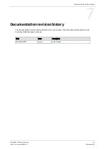
Page 29: ...lists the date issue number and description of all publications of the Dolby DSR1090 Owner s Manual Date Issue Description 16 October 2022 Issue 1 Initial release Documentation revision history Dolby DSR1090 Owner s Manual 29 Issue 1 Part number 8800304 16 October 2022 ...

Reviews: