21
BH 5910 / 200217 / 190A
Switch
1
Function
Switch
1
No / Sensors
Control mode
Operation mode
Feedback circuit
for external
contacts
0
E-stop
0
1
2
3
4
5
6
7
4
3
8
6 E-stop button
3
3
6
6
2 channel
2 channel
1 channel
1 channel
2 channel
2 channel
1 channel
1 channel
Auto-Start
Manual start
Auto-Start
Manual startt
Auto-Start
Manual startt
Auto-Start
Manual start
no
no
no
no
yes
yes
yes
yes
1
Light curtains (LC)
0
1
2
3
4
3 Light curtains
3
3
2 channel
2 channel
2 channel
2 channel
Auto-Start
Manual startt
Auto-Start
Manual start
no
no
yes
yes
2
Light cu E-stop
(1 E-stop button,
2-channel, manual start
0
1
2
3
2
2 Light curtains
2
2
2 channel
2 channel
2 channel
2 channel
Auto-Start
Manual start
Auto-Start
Manual start
no
no
yes
yes
3
Gate monitor
0
1
2
3
4
5
6
7
8
9
4
3
2
1
2 Gate switches
1
3
1
2
1
2 NO contacts
2 NO contacts
2 C/O contacts
2 C/O contacts
3 NO contacts
2 C/O contacts, 1 NO
2 NO contacts
2 C/O contacts
3 NO contacts
2 C/O contacts, 1 NO
without simulation button
with simulation button
without simulation button
with simulation button
with simulation button
with simulation button
with simulation button
with simulation button
with simulation button
with simulation button
no
no
no
no
no
no
yes
yes
yes
yes
4
Gate m E-stop
(1 E-stop button,
2-channel, manual start)
0
1
2
3
4
5
2
1
1 Gate switches
2
1
1
2 NO contacts
2 C/O contacts
3 NO contacts
2 NO contacts
2 C/O contacts
3 NO contacts
with simulation button
with simulation button
with simulation button
with simulation button
with simulation button
with simulation button
no
no
no
yes
yes
yes
5
2-hand safety
0
1
2
3
4
5
6
7
8
9
1
2
3
4
1 button pairs
2
1
2
3
1
2 NO contacts
2 NO contacts
2 NO contacts
2 NO contacts
2 NO contacts
2 C/O contacts
2 NO contacts
2 NO contacts
2 NO contacts
2 C/O contacts
no
no
no
no
no
no
yes
yes
yes
yes
6
2-hand E-stop
(1 E-stop button, 2-chan-
nel, manual start)
0
1
2
3
4
5
1
2
1 button pairs
1
2
1
2 NO contacts
2 NO contacts
2 C/O contacts
2 NO contacts
2 NO contacts
2 C/O contacts
no
no
no
yes
yes
yes
7
not permitted
8
not permitted
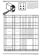
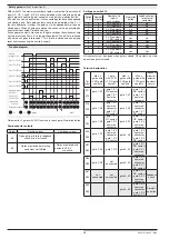
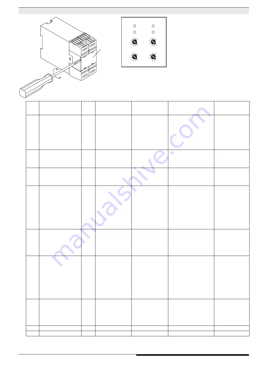
Unit settings
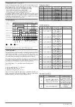
The selection of the function of BH 5910 is done
via 4 rotational switches behind the front cover
of the unit (see drawing on the left). The 2 swit-
ches on the left set processor 1 (ch 1) and the 2
switches on the right set processor 2 (ch 2). Both
processors must have the same setting. On both
upper switches (1) the function is selected, on
both lower switches (10) the number of sensor
circuits, control and operation mode and the feed
back circiuit option is selected.
plate
M2929
0
3
6
9
0
3
6
9
0
3
6
9
0
3
6
9
ch1
ch2
10
1
M8055
Inside view


