


28
BH 5910 / 200217 / 190A
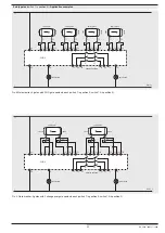
Safety gates
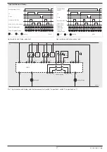
(switch 1 in position 3)
With switch 10 the maximum number of gates is selected. Open (unused)
inputs (S_1/S_2 and S_3/S_4) have to be linked with a wire bridge. If gate
inputs are not used the type of control has to be with simulation button.
K1 and K2 can only be activated, if all connected gates have been opened
and closed again. Both gate contacts have to be operated within 3 s. If
the time difference is longer, the gate has to be opened before it can be
closed again. When all gates are closed the unit can also be activated by
an external connected Simulation button.
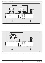
If changeover contacts are used on the gate switches the switchover time
has to be less then 50 ms. If it is longer the outputs K1 and K2 are switched
off and the unit gives failure code 7. This failure is stored and can only be
reset by disconnecting the auxiliary supply.
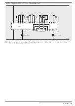
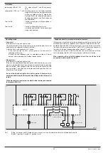
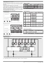
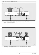
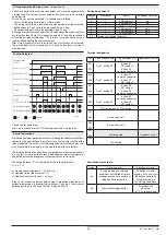
Gate monitor, 2 gates with 3 NO contacts for each gate, Simulation button
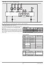
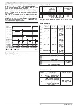
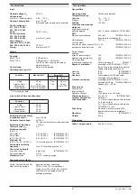
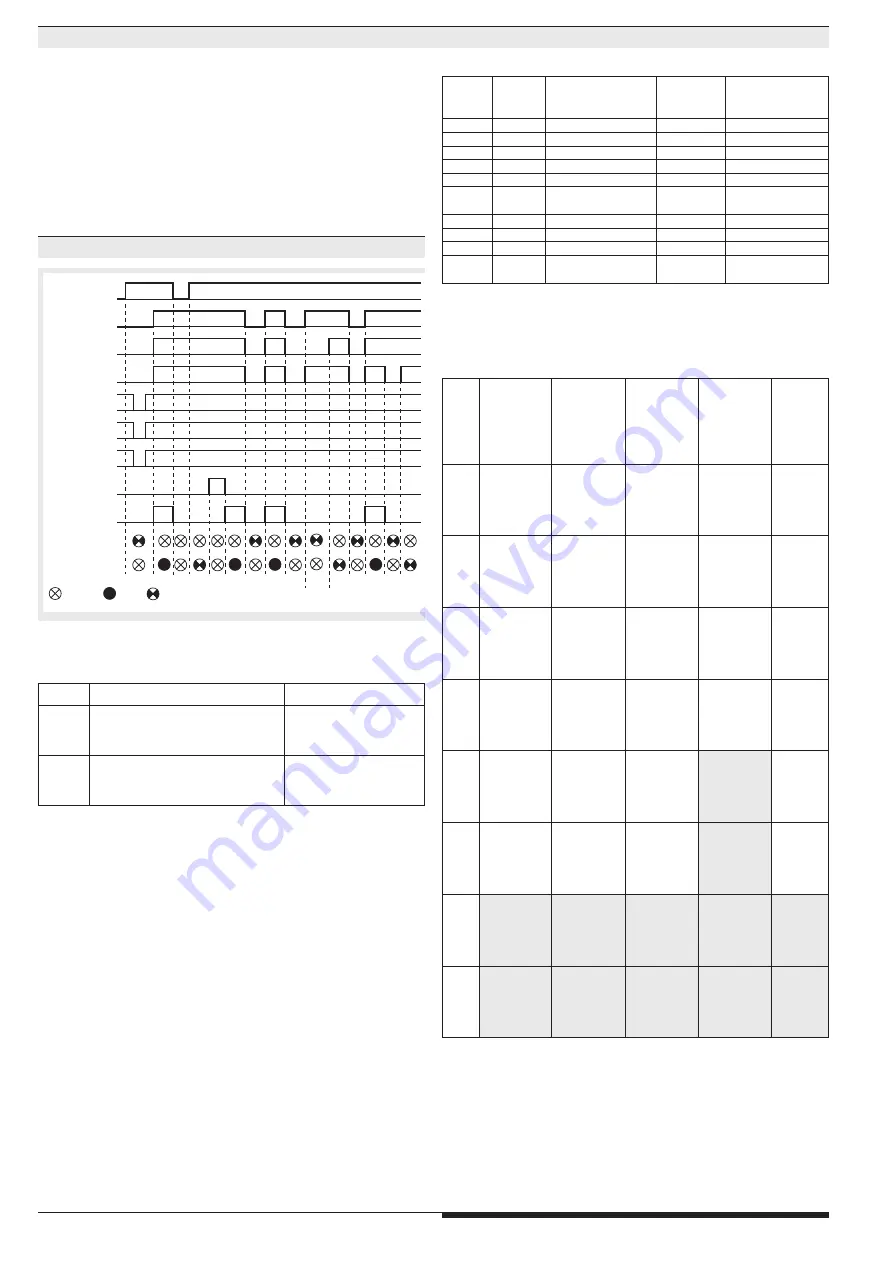
Function diagram
NO contacts must be closed when gate is closed, NC contacts must be
open when gate is closed.
Gate 2 S1 (S23/S24)
Auxiliary
voltage (A1/A2)
Gate 2 S2 (S31/S32)
Gate 1 S1 (S11/S12)
Gate 2 S3 (S33/S34)
Gate 1 S2 (S13/S14)
Simulation button
(S43/S44)
Gate 1 S3 (S21/S22)
K1/K2 (13-14,
23-24, 33-34)
48 (gate open
or failure)
58 (all gates closed)
: off
: on
: flashing
M8437
>3s
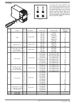
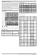
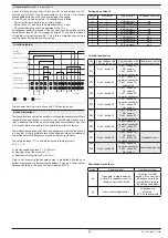
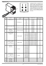
Settings on switch 10
Switch
10
Number
of gates
Number and
type of
gate switches
Simulation
button
Feedback circuit
for external
contactors
0
4
2 NO contacts
no
no
1
3
2 NO contacts
yes
no
2
2
2 C/O contacts
no
no
3
1
2 C/O contacts
yes
no
4
2
3 NO contacts
yes
no
5
1
2 C/O contacts
+ 1 NO contact
yes
no
6
3
2 NO contacts
yes
yes
7
1
2 C/O contacts
yes
yes
8
2
3 NO contacts
yes
yes
9
1
2 C/O contacts
+ 1 NO contact
yes
yes
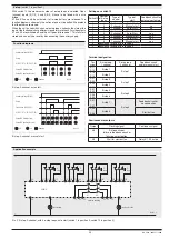
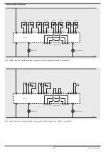
Terminal designation
Ter-
minal
Max. 2
gates with
3 NO gate
contacts
1 gate
with 2 C/O
+ 1 NO gate
contact
Max. 4
gates with
2 NO gate
contacts
Max. 2
gates with
2 C/O gate
contacts
Feedback
circuit for
external
contacts
simula-
tion
S11
S12
gate 1, S1
gate 1, S1
NO contact
gate 1, S1
common
connector
gate 1, S1
gate 1, S1
NO contact
gate 1, S1
common
connector
S14
S13
gate 1, S2
gate 1, S1
common
connector
gate 1, S1
NC contact
gate 1, S2
gate 1, S1
common
connector
gate 1, S1
NC contact
S21
S22
gate 1, S3
gate 1, S2
NC contact
gate 1, S2
common
connector
gate 2, S1
gate 1, S2
NC contact
gate 1, S2
common
connector
S24
S23
gate 2, S1
gate 1, S2
common
connector
gate 1, S2
NO contact
gate 2, S2
gate 1, S2
common
connector
gate 1, S2
NO contact
S31
S32
gate 2, S2
gate 1, S3
gate 3, S1
gate 2, S1
NO contact
gate 2, S1
common
connector
S34
S33
gate 2, S3
not
connected
gate 3, S2
gate 2, S1
common
connector
gate 2, S1
NC contact
S41
S42
not
connected
not
connected
gate 4, S1
gate 2, S2
NC contact
gate 2, S2
common
connector
Feedback
circuit
S44
S43
gate 4, S2
gate 2, S2
common
connector
gate 2, S2
contact NO
Simulati-
on button
Semiconductor outputs
Output
Flashing signal
Continuous signal
48
Open gate or failure in feedback
circuit or in start circuit
58
Gates are closed but starting
conditions not fulfilled
Gates are closed and
contacts K1, K2
are active


