16
LG 5925 / 26.02.18 en / 972
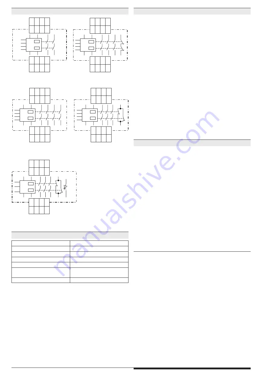
LG 5925.48
S33
A1
+
S11
A2
S34
13
S12
14
41
23
S21
24
42
33
S22
34
M8553
S12
S22
S33
S34
A1+ S11
A2
S21
K1
K2
13 23 33
41
14 24 34
42
LG 5925.04
S33
A1
+
S11
A2
S34
13
S12
14
43
23
S21
24
44
33
S22
34
M8552
S12
S22
S33
S34
A1+ S11
A2
S21
K1
K2
13
23
33
43
14
24
34
44
LG 5925.02
S33
A1
+
S11
A2
S34
13
S12
14
23
S21
24
S22
M8573_a
S12
S22
S33
S34
A1+ S11
A2
S21
K1
K2
13
23
14
24
58
A1
+
S11
A2
S34
13
S12
14
41
23
S21
24
42
33
S22
34
M9721
S12
S22
S34
A1+ S11
A2
S21
K1
K2
13 23 33
41 +
14 24 34
42
58
K1/K2
LG 5925.54
LG 5925.03
S33
A1
+
S11
A2
S34
13
S12
14
41
23
S21
24
42
33
S22
34
M10536
S12
S22
S33
S34
A1+ S11
A2
S21
K1
K2
13 23 33 41
14 24 34 42
Line fault detection on On-button:
The line fault detection is only active when S12 and S22 are switched
simultaneously. If The On-button is closed before S12, S22 is connected
to voltage (also when line fault across On-Button), the output contacts will
not close. A line fault across the On-button which occurred after activation
of the relay, will be detected with the next activation and the output con-
tacts will not close.
The terminal S21 permits the operation of the device in IT-systems with
insulation monitoring, serves as a reference point for testing the control
voltage and is used to connect the E-stop loop when cross fault moni-
toring is selected.
Connecting the terminal S21 to the protective ground bridges the internal
short-circuit protection of Line A2 (-). The short-circuit protection of line
A1 (+) remains active.
To alter the functions automatic start - manual start and with or without
cross fault monitoring, the switches S1 and S2 are used. These are loca-
ted behind the front cover (see unit programming).
The setting with or without cross fault monitoring on E-stop buttons is
made with S1 (not for LG 5925.54). The LG 5925.54 has always cross
fault monitoring.
S2 is used to change between automatic an manual restart. On automatic
start also the terminals S33 - S34 have to be linked. For connection please
see application examples.
Input circuit
Nominal Voltage U
N
:
LG 5925:
AC/DC 24 V, AC 110 ... 115 V, AC 230 V
LG 5925.54:
AC/DC 24 V
Voltage range
AC / DC
at 10% residual ripple:
0.9 ... 1.1 U
N
AC:
0.85 ... 1.1 U
N
Nominal consumption at U
N
:
DC approx. 1.5 W
AC approx. 3.7 VA
Min. Off-time:
250 ms
Control voltage on S11 at U
N
:
DC 22 V at AC/DC units
DC 24 V at AC units
Control current typ. over
S12, S22:
LG 5925:
30 mA at U
N
LG 5925.54:
25 mA at U
N
Min. voltage on S12, S22
when relay activated:
DC 20 V at AC/DC units
DC 19 V at AC units
Short-circuit protection:
Internal PTC
Overvoltage protection:
Internal VDR
Output
Contacts
LG 5925.02:
2 NO contacts
LG 5925.04:
4 NO contact
LG 5925.03 ,
LG 5925.48, LG 5925.54:
3 NO, 1 NC contact
The NO contacts are safety contacts.
The NC contacts 41-42 can only be used for monitoring.
Operate delay typ. at U
N
:
Manual start:
30 ms
automatic start:
350 ms
Release delay typ. at U
N
:
Disconnecting the supply:
150 ms at AC units
50 ms at DC units
Disconnecting S12, S22:
130 ms at AC units
50 ms at DC units
Contact type:
forcibly guided
Nominal output voltage:
AC 250 V
DC see limit curve for arc-free operation
Thermal current I
th
:
max. 8 A per contact
see current limit curve
Terminal designation
Signal description
A1+
+ / L
A2
- / N
S12, S22, S33, S34
Inputs
S11, S21
Outputs
13, 14, 23, 24, 33, 34, 43, 44
Forcibly guided NO contacts for
release circuit
41, 42
Forcibly guided indicator output
Circuit Diagrams
Notes
Connection Terminals
Technical Data


