1
07.10.15 en / 477
Safety Technique
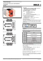
Multi-Function Safety System SAFEMASTER M
Control Unit
BH 5911
•
According to
- Performance Level (PL) e and category 4 to EN ISO 13849-1: 2008
- SIL Claimed Level (SIL CL) 3 to IEC/EN 62061
- Safety Integrity Level (SIL 3) to IEC/EN 61508
•
For emergency stop function, the following inputs
and outputs are available:
Inputs:
4 monitored start inputs, or
3 start inputs and 1 stop input and
2 Emergency stop inputs
Outputs:
3 NO contacts, or
2 NO contacts/1 NC monitoring contact
•
Parallel connection of several SAFEMASTER M-systems possible
•
The functions are selected via rotary switch
- 1 Emergency stop circuit, 2-channel
- 2 Emergency stop circuits, single-channel
- 1 Emergency stop circuit, 2-c 1 stop single channel
•
Auto or manual start
•
2 semiconductor outputs for status indication
•
LEDs for status indication
•
Overvoltage and undervoltage monitoring function with error indication
•
Permanently monitored feedback loop to connect external contactors
•
Broken wire and short circuit monitoring function with error indication
•
Width: 45 mm
0247385
Realization of fail-safe control circuits for protection of people and machinery
Applications
X11
A1
(+)
S11
13
S13
23
X12
33
X11
A2
(-)
T1
14
T3
24
X12
34
S14
48
(-)
58
S12
Y1
T2
(-)
Y2
T4
M8743
48
58
A1+
A1+
S11
(-) (-)
S12 S13 S14 T1
X11 X11 X12 X12
T2 T3 T4
Y1 Y2
A1(+)
A2(-)
33
23
13
34
24
14
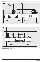
BH 5911.03
Circuit Diagrams
X11
A1
(+)
S11
11
S13
23
X12
33
X11
A2
(-)
T1
12
T3
24
X12
34
S14
48
(-)
58
S12
Y1
T2
(-)
Y2
T4
M8744
48
58
A1+
A1+
S11
(-) (-)
S12 S13 S14 T1
X11 X11 X12 X12
T2 T3 T4
Y1 Y2
A1(+)
A2(-)
33
23
11
34
24
12
BH 5911.22
General Information SAFEMASTER M
The maximum configuration of the SAFEMASTER M multi-function safety
system is as follows:
•
the control unit BH 5911
•
up to 3 input modules BG/BH 5913, or BG/BH 5914, BH/BH 5915
•
up to 3 output modules BG 5912
•
1 diagnostic module BG 5551 for CANopen, or
•
1 diagnostic module BG 5552 for Profibus-DP
The BH 5911 controls the whole system.
The input/output modules can be used to expand the control unit in a
modular way into a multi-functional safety system.
To transmit status messages of the individual modules to a moni to ring or
control unit, one of the following diagnostic modules may be connected:
•
BG 5551 for CANopen
•
BH 5552 for Profibus-DP
Input Terminal Assignment
Terminal
Signal
S11
Emergency stop button 1
S12
S13
Emergency stop button 2
S14
X11-T1
Start button 1
X11-T2
Start button 2
X12-T3
Start button 3
X12-T4
Start button 4 or stop
Y1-Y2
Feedback loop for external contact extensions
Approvals and Markings
A025518
Canada / USA
All data in this list are in correspondence with the technical equipment used at the time of this
version. We reserve the right to implement technical improvements and changes at any time.


