2
07.10.15 en / 477
Notes
•
Settings to the unit must be performed by skilled personnel while
the unit is disconnected.
•
Before the front cover is removed, antistatic precautions must be
observed.
Automatic Start
Automatic start is only performed when the supply voltage is switched on
or when the Emergency stop or stop function has been reset (with switch
positions 7 to 9, also after undervoltage).
All other errors nevertheless require confirmation by a start input.
Manual Start
Stop
Instead of the fourth start button, an additional stop input (NC contact)
can be connected. It is assigned only to the control unit and treated like an
additional single-channel emergency stop button.
This means that the safety outputs assigned to the control unit can only be
activated if neither the emergency stop or the stop button are activated.
Green LEDs (left):
on, when all inputs are present and start
button activated.
Green LEDs (right):
on, when the safety outputs of the
control unit are activated.
White LEDs Run 1 and
Run 2 and semiconduc-
tor outputs 48 and 58: Indicate the current status of the
control unit.
Indication
If operating function 2, 6 or 7 is selected, an assignment to the start
input 4 will remain ineffective in all connected modules.
Setting of Functions
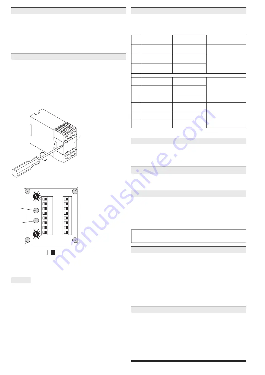
The control unit is assigned to the start inputs T1…T4 and the safety out-
puts via the DIP switches. The input function is set by means of the rotary
switches. To prevent accidently adjustments the setting switches are covered
by a front plate and are redundant.
The control unit is supplied with two fitted terminating connectors. When the
control unit is equipped with extension modules, remove these ter -minating
connectors and plug them to the last interconnected device. When a diagnostic
module is used, it is connected instead of the terminating con -nector.
The start input must not be pressed for more than 3 seconds to start the sy-
stem. Alternatively, several start inputs may be assigned to one module.
plate
M2929
M9039_
b
0
0 1
1
1
2
2
3
3
4
4
5
5
6
6
7
7
8
8
2
2
3
4 output
start input
Mod3
T1
Mod2
T2
Mod1
T3
Base
T4
Mod3
T1
Mod2
T2
Mod1
T3
Base
T4
5
6
7
7
8
white LED
"run 1"
white LED
"run 2"
S1
S2
green LED "K1"
green LED "en 1"
green LED "en 2"
9
9
green LED "K2"
off
on
Lock-Out after Undervoltage
When an undervoltage is detected, the whole system (including any ex-
tension modules) turns off (auto reset). There are two different options of
auto restart:
1. The system de-energises the safety outputs as soon as undervoltage
has been detected.
There after the system will only reset after complete removal of voltage.
2. The system de-energises the safety outputs and remains de-energized
until supply voltage is back to a permissible value. Then, the system is
restarted.
Shortcircuit and Crossfault Detection
The control unit has an integrated dynamic shortcircuit and crossfault
detection. This feature can only be used when the inputs are switched by
contacts and if they are only connected to one safemaster input.
To connect light curtains of type 4 or to operate several safemaster M
units from common sensors a special wiring has to be chosen.
Notes:
•
Settings to the unit must be performed by skilled personnel while the
unit is disconnected.
•
Before the front cover is removed, antistatic precautions must be
observed.
base = Output of control Unit
mod = Output of output module
Sw
Function
Start input selection
Start function s
etting conditions
0
1 E-stop or 1 LC*
2 channel
4 start inputs
Automatic start
lock-out following
undervoltage
1
2 E-stop
1 channel
4 start inputs
2
1 E-stop or 1 LC*
2 channel
3 start inputs
1 Stop
3
not permitted (error 5)
4
1 E-stop or 1 LC*
2 channel
4 start inputs
Manual start
5
2 E-stop
1 channel
4 start inputs
6
1 E-stop or 1 LC*
2 channel
3 start inputs
1 Stop
7
1 E-stop or 1 LC*
2 channel
3 start inputs
1 Stop
Automatic start
following undervoltage,
restart after the voltage
has returned to the
permissible value
8
1 E-stop or 1 LC*
2 channel
4 start inputs
9
2 E-stop
1 channel
4 start inputs
* LC = light curtain


