17
UF 6925 / 30.08.17 en / 895
Technical Data
Technical Data
Standard Type
Input
Nominal Voltage U
N
:
DC 24 V, DC 8 ... 36 V
The power supply shall meet the
requirements of SELV / PELV
Voltage range
DC 24 V:
0.8 ... 1.1 U
N
Nominal consumption at
DC 24 V:
< 1.6 W
DC 8 ... 36 V:
< 2.2 W
Min. Off-time:
150 ms
Control voltage on S11
at not activated device:
DC 23 V at U
N
Control current typ. over
S12, S22:
30 mA at U
N
Min. voltage on terminal S12
at not activated device:
DC 19 V
Short-circuit protection:
Internal PTC
Overvoltage protection:
Internal VDR
Output
Contacts
UF 6925.03:
3 NO contacts
UF 6925.22:
2 NO contacts, 1 NC contact
The NO contacts are safety contacts.
The NC contacts 31-32 can only be used for monitoring.
Operating time at U
N
:
< 350 ms
Release delay at U
N
:
in case of break of
supply voltage:
DC 24 V:
< 20 ms
DC 8 ... 36 V:
< 90 ms
in case of break of S12, S22:
< 25 ms
Contact type:
Relay,
forcibly guided
Thermal current I
th
:
max. 8 A
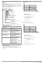
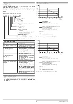
(see limit curve for arc-free operation)
Switching capacity
to AC 15
NO contact:
3 A / AC 230 V
IEC/EN 60 947-5-1
NC contact:
1 A / AC 230 V
IEC/EN 60 947-5-1
to DC 13
NO contact:
2 A / 24 V
IEC/EN 60 947-5-1
NC contact:
2 A / 24 V
IEC/EN 60 947-5-1
to DC 13
NO contact:
4 A / 24 V at 0.1 Hz IEC/EN 60 947-5-1
NC contact:
4 A / 24 V at 0.1 Hz IEC/EN 60 947-5-1
Electrical life
at AC 230 V, 8 A, cos
ϕ
= 1:
> 1.0 x 10
5
switching cycles
(at 1 s On, 1s Off)
Permissible operating
frequency:
max. 1 200 Schaltspiele / h
Short circuit strength
max. fuse rating:
8 A gL
IEC/EN 60 947-5-1
line circuit breaker:
B 6 A
Mechanical life:
> 40 x 10
6
switching cycles
General Data
Operating mode:
Continuous operation
Temperature range
Operation:
- 25 ... + 55
°
C
Storage:
- 25 ... + 85
°
C
Altitude:
< 2,000 m
Clearance and creepage
distances
Rated impuls voltage /
pollution degree:
4 kV / 2
IEC 60 664-1
EMC:
IEC/EN 61 326-3-1
Interference suppression
DC 24 V:
Limit value class B
EN 55 011
DC 8 ... 36 V:
Limit value class A*
)
EN 55 011
*) The device is designed for the usage
under industrial conditions (Class A,
EN 55011). When connected to a low
voltage public system (Class B,
EN 55011) radio interference can be
generated. To avoid this, appropriate
measures have to be taken.
Degree of protection:
Housing:
IP 40
IEC/EN 60 529
Terminals:
IP 20
IEC/EN 60 529
Housing:
thermoplastic with V0 behaviour
according to UL subject 94
Vibration resistance:
Amplitude 0,35 mm
Frequenz 10 ... 55 Hz, IEC/EN 60 068-2-6
Climate resistance:
25 / 055 / 04
IEC/EN 60 068-1
Terminal designation:
EN 50 005
Mounting:
DIN rail
IEC/EN 60 715
Weight:
140 g
Dimensions
Width x height x depth
:
17.5 x 110 x 120 mm
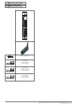
UF 6925.03/61 DC 8 ... 36 V
Article number:
0067556
•
Output:
3 NO contacts
•
Nominal voltage U
N
:
DC 8 ... 36 V
•
Width:
17.5 mm
The safety functions were not evaluated by UL. Listing is accomplished
according to requirements of Standard UL60947, “general use
applications”
Standards:
- ANSI/UL 60947-1, 5
th
Edition (Low-Voltage Switchgear and Controlgear
Part1: General rules)
- ANSI/UL 60947-5-1, 3
th
Edition (Low-Voltage Switchgear and Controlgear
Part5-1: Control circuit Devices an Switching Elements - Electro-
mechanical Control Circuits Devices)
- CAN/CSA-C22.2 No. 60947-1-13, 2
nd
Edition (Low-Voltage Switch-
gear and Controlgear - Part1: General rules)
- CAN/CSA-C22.2 No. 60947-1-14, 1
st
Edition (Low-Voltage Switch-
gear and Controlgear - Part5-1: Control circuit Devices an Switching
Elements - Electromechanical Control Circuits Devices)
Switching capacity:
UF 6925.03:
Pilot duty B300, Q300
6A 250Vac Resistive
6A 24Vdc Resistive
UF 6925.22:
Pilot duty B300, Q300
8A 250Vac Resistive
8A 24Vdc Resistive
Wire connection:
min. 60°C copper conductors
AWG 28 - 14
nfo
Technical data that is not stated in the UL-Data, can be found
in the technical data section.
UL-Data


