background image

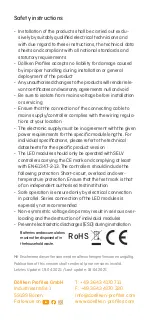
Sicherheitshinweise

•  Die Installation der Produkte muss unter Beachtung der 

vorliegenden Anleitungen, technischen Datenblätter 
sowie Einhaltung aller nationalen gesetzlichen Vorgaben 
und Normen erfolgen

•  Döllken Profiles übernimmt keinerlei Haftung für durch 

unsachgemäße Handhabung entstandene Schäden bei 
Montage oder generellem Einsatz der Produkte.

•  Selbst durchgeführte Änderungen an den Produkten 

führen zum Erlöschen der gültigen Zertifikate und Garan-
tievereinbarungen

•  Die Verbindung zur Netzspannung muss zwingend vor 

jeder Installation oder Wartungsarbeit an den Produkten 
unterbrochen werden

•  Es ist darauf zu achten, dass die Verbindung von 

Anschlusskabel zu Spannungsversorgung/Steuerungs- 
einheit entsprechend der benötigten Schutzart des 
Installationsortes ausgeführt ist

•  Die genutzte Elektronik muss zu den entsprechenden, 

leistungsbezogenen Daten der individuellen Modullängen 
genügen

•  Die LED-Module sollten nur mit SELV–Betriebsgeräten 

betrieben werden, die das CE-Zeichen tragen und die 
Konformität nach mindestens der Norm EN-61347-2-13 
bestätigen. Betriebsgeräte sollten folgende Schutz-
maßnahmen aufweisen: Kurzschlussschutz, Überlast-
schutz und Übertemperaturschutz. Achten Sie dabei 
auf das Prüfzeichen eines unabhängigen berechtigten 
Prüfinstitutes

•  Nur die elektrische Parallelschaltung ermöglicht einen 

sicheren Betriebszustand. Von der elektrischen Reihen-
schaltung der LED-Module wird ausdrücklich abgeraten. 
Unsymmetrische Spannungsabfälle können zu einer 
starken Überlastung und Zerstörung einzelner Module 
führen

•  Vermeiden Sie elektrostatische Entladungen (ESD) bei 

der Installation

RoHS

Batterien und Akkus 
dürfen nicht in den  
Hausmüll!

Summary of Contents for Cubica Light System

Page 1: ...Cubica Light System Starter Set Verarbeitungs anleitung Zur Montage benötigen Sie Seitenschneider oder Elektrikerzange Zange Schrauben dreher Döllken Sockelleisten schere 5905392 ...

Page 2: ...inder LED Band zu LED Band LED Anschlusskabel Y Verteilkabel Netzteil Trafo für 230 V Steckdose für max 7 2 m LED Band ausgelegt Zusätzlich erhältlich nicht im Starter Set enthalten Steuerungs Set mit H Funkstecker und I Funkschalter inkl Batterie CR2032 Unser Verarbeitungsvideos dazu finden Sie online unter www licht sockelleiste de A B C D E F G H I ...

Page 3: ... Das Netzteil istfürmaximal 7 2 m LED Band ausgelegt Bevordas LED Band zugeschnitten und verklebtwird sollte undegingtein Funktionstestdurch geführtwerden Aufden Seiten 10 12 finden Sie eineAuflistung möglicher Fehlerquellen bei Funktionsstörungen sowieAllgemeine Installations und Sicherheitshinweise Die Montageanleitung der Grund und Deckprofile finden Sie online unter www licht sockelleiste de i...

Page 4: ... LED Anschluss kabel E mit richtiger Polung einführen und mit einer Zange zudrücken Netz teil G verbinden um einen Funktionstest durchzuführen LED Band auf gewünschte Länge zuschneiden LED Band mit Seitenschneider oder Elektrikerzange an der Markierung zuschneiden alle 5 cm möglich ACHTUNG nuran dervorgesehenen Markierung schneiden ansonsten ist der 5cm Abschnitt nicht mehr funktionstüchtig 2 3 E ...

Page 5: ...s LED Band mittels des aufgetragenen Fixierungsbandes in das Grundprofil gleichmäßig eingeklebt Schutzfolie des aufgetragenen Fixierungsbandes dabei stufenweise entfernen DirekterAnschluss von einem einzelnen LED Band an das Netzteil 0 A B C D E F G H I J K L M 4 4a click C A E E G C C E G E G ...

Page 6: ... DerAnschluss des zweiten LED Bandes kann analog des Punkt 2 derVerarbeitungsanleitung ausgeführt werden Y Verteilkabel F mit Netzteilstecker G verbinden und in den unteren Teil des Grundprofils platzieren Erneuter Funktionstest bevor Deckprofil montiert wird 1 Anschluss eines zweiten LED Bandes mit Hilfe des Y Verteilkabels N click click LED Anschlusskabel können auch nach Bedarf etwas eingekürzt...

Page 7: ...äßig eingekleben Schutzfolie des aufgetragenen Fixierungsbandes dabei stufenweise entfernen Y Verteilkabel F mit Netzteilstecker G verbinden und Kabel im unteren Teil des Grundprofils platzieren Erneuter Funktionstest bevor Deckprofil montiert wird 1 Anschluss eines weiteren LED Bandes mit Hilfe des Y Verteilkabels und 2 5 m Verlängerungskabels 4c C F E B G C C G E E F B ACHTUNG Das Netzteil ist f...

Page 8: ...inder LED Band zu LED Band D können zur Fortführung von LED Band Abschnitten verwendet werden um eine nahtlose Verbindung herzustellen Sonderfall Cubica LS Lightup Lichtoben zur Verbindung der LED Band Abschnitte bei Verle gung von Außenecken der Cubica LS Light up Licht oben wird ein zusätzliches Kabelset Art Nr 5905798 benötigt Dieses muss bei Bedarf zusätzlich gekauft werden und ist nicht im St...

Page 9: ...s Deckprofils Hinweise zur Montage des Deckprofils finden Sie in der Verarbeitungsanleitung Cubica Light System Grund und Deckprofil bzw online unter www licht sockelleiste de 7 Einfach mit dem Smartphone scannen ...

Page 10: ...ntakt liegt der auf dem Band mit Minus gekennzeichnet ist Dementsprechend roter Draht an Plus 24V der PTF Stecker Verbinder richtig herum gedreht ist Das Band kann oben und unten angeschlossen werden um die Polung drehen zu können siehe 1 Punkt Der PTF Stecker hat Kontakte auf der dickeren Seite d h wenn der Stecker gedrehtwerden muss müssen u U die Kontakte auf der Unterseite des LED Bandes benut...

Page 11: ...verdrillen das aufgerollte LED Modul nicht werfen sondern auf einer horizontalen Fläche gleichmäßig entrollen Krafteinwirkung Zugbelastung oder sonstige mechanis che Einflüsse im Bereich des Anschlusses ist während der Installation zu vermeiden und durch entsprechende Sicherung der Kabel im installierten Zustand komplett auszuschließen Während der Installation mechanische Einflüsse auf jeden Berei...

Page 12: ...tigten Schutzart des Installationsortes ausgeführt ist Die genutzte Elektronik muss zu den entsprechenden leistungsbezogenen Daten der individuellen Modullängen genügen Die LED Module sollten nur mit SELV Betriebsgeräten betrieben werden die das CE Zeichen tragen und die Konformität nach mindestens der Norm EN 61347 2 13 bestätigen Betriebsgeräte sollten folgende Schutz maßnahmen aufweisen Kurzsch...

Page 13: ...Cubica Light System Starter Set Installation instruction For the installation you need Side cutters or electrician s pliers Screwdriver Döllken skirting scissors 5905392 Pliers ENG ...

Page 14: ...or LED tape to LED tape LED connection cable Y distribution cable Power supply transformer for 230 V socket designed for max 7 2 m LED tape Additionally available not included in the starter set Control set with H radio plug and I radio switch incl battery CR2032 Our processing videos for this can be found online www cubica light de A B C D E F G H I ...

Page 15: ...tention The powersupplyis designed fora maximum of 7 2 m LEDtape Beforethe LEDtape is cutand glued a functiontestshould be carried out On pages 10 12youwill find a listofpossible sources of errorinthe eventofmalfunctions aswell as general instal lation and safetyinstructions The mounting instructions forthe base and cover profiles can be found online www licht sockelleiste de in the app or in our ...

Page 16: ...D tape to cable connector Insert LED connec tion cable E with correct polarity and press shut with pliers Connect the power supply unit G to perform a function test Cut LED tape to desired length cut the LED tape at the marking every 5 cm possible with side cutters or electrician s pliers ATTENTION cutonlyatthe intended marking cut otherwisethe 5cm section is no longerfunctional 2 3 E C A E C A G ...

Page 17: ... recess 1 cm the LED tape is glued evenly into the base profile using the applied fixing tape remove the protective film of the applied fixing tape step by step Direct connection of a single LED strip to the power supply 0 A B C D E F G H I J K L M 4 4a click C A E E G C C E G E G ...

Page 18: ... strip can be connected in the same way as in point 2 of the processing instructions connectY distribution cable F with power supply plug G and place it in the lower part of the base profile Renewed function test before cover profile is mounted 1 Connection of a second LED strip using the Y distribution cable 0 click click LED connection cables can also be shortened slightly as needed to better st...

Page 19: ...e the protective film of the applied fixing tape step by step connectY distribution cable F with power supply plug G and place cables in the lower part of the base profile Before the cover profile is mounted repeat the function test 1 Connection of another LED strip using the Y distribution cable and 2 5 meter extension cable 4c C F E B G C C G E E F B The power supply is designed for a maximum of...

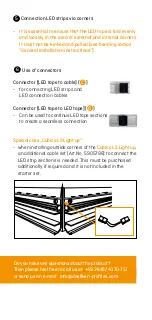
Page 20: ...on cables Connector LED tape to LED tape D Can be used to continue LED tape sections to create a seamless connection Special case Cubica LS Lightup when installing outside corners of the Cubica LS Light up an additional cable set Art No 5905798 to connect the LED strip sections is needed This must be purchased additionally if required and it is not included in the starter set 5 6 Do you have any q...

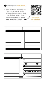
Page 21: ...the cover profile Instructions for mounting the cover profile can be found in the processing instructions Cubica Light System base and cover profile or online www cubica light de en 7 Just scan with your smartphone ...

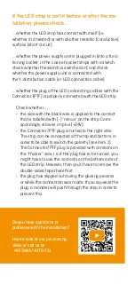
Page 22: ...e black wire is applied to the contact that is labelled with minus on the strip Corre spondingly red wire on plus 24V the Connector PTF plug is turned to the right side The strip can be connected at the top and bottom in order to be able to switch the polarity see item 1 The Connector PTF plug is provided with contacts on the thicker side i e if the plug has to be turned you might have to use the ...

Page 23: ...or tensioning the connec tions of the strips during installation and secure the wiring to fully exclude this after installation Avoid bringing mechanical forces to bear on any part of the product during installation Exercise particular care when installing lengths in excess of 1 5 m to prevent damage to the conducting foil or electronic components The materials used will allow changes in length of...

Page 24: ...ical datasheets forthe specific productversion The LED modules should only be operated with SELV controllers carrying the CE mark and complying at least with EN 61347 2 13 The controllers should include the following protection Short circuit overload and over temperature protection Ensure thatthe test mark is that of an independent authorised test institution Safe operation is ensured only by elec...

Reviews: