16
GB
GB
GB
GB
GB
GB
GB
GB
GB
GB
GB
GB
GB
GB
GB
GB
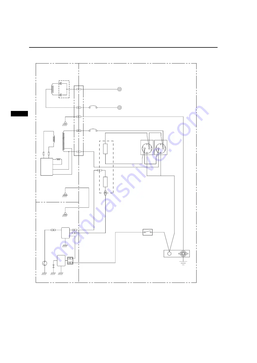
14.WIRING DIAGRAM
GE-1100 (50Hz-230V)
Blk :
Black
Wiring color code
Blk/W : Black/White
Blu :
Blue
LBlu : Light
blue
Brn :
Brown
Brn/W : Brown/White
Grn :
Green
Grn/W : Green/White
Org :
Orange
Gry : Gray
R :
Red
W :
White
Y :
Yellow
Grn/Y : Green/Yellow
W/Blk : White/Black
Pur :
Purple
W
Brn
CONTROL PANEL
ENGINE
GENERATOR
+
-
DC coil
Org
Gry
Engine switch
Oil sensor
R
Main coil
Ignition
coil
DC output
terminal
Grn/Y
Blk
Earth
plate
Earth
(ground)
terminal
R
W
W
Blk
Grn/Y
Grn/Y
Grn/Y
Grn/Y
AVR
Brush(
-
)
Brush(+)
Field coil
Spark plug
DC circuit
breaker
LAMP "RUN"
LAMP "OIL"
INDICATOR UN
Exciter
coil
AC
receptacle
Oil sensor
Control UN
AC circuit
breaker
Diode Rectifier
R
Summary of Contents for GE-1100
Page 3: ...LW A ...


