background image

G  

THERMASREG

®

  FS-20 

Rev.  2020 - V12

Electronic frost protection thermostat ⁄ frost monitor 

THERMASREG

®

 FS-20 

with switching relay output, continuous temperature and valve output 

(summation output 0–10V) and control and cascading output (0–10V), optionally with connection for heating element, in an impact-resistant plastic 

housing with quick-locking screws, with display by default, with fully active sensorrod made from copper.  The frost monitor is used to monitor air 

conditioning systems, heat exchangers, heating registers and similar systems, and protects against frost damage and freezing. Falling below the 

limit value is detected at the coldest measuring point of the capillary tube, the sensor rod is active along its entire length. Uses internal diagnostics 

to detect capillary breakage, power failure or electric damage to the sensor as an error and the relay automatically switches to frost. The innovative 

2-phase frost protection thermostat enables simple combination of several devices (cascading) for demand-oriented, comprehensive frost monitoring. 

The delivery scope includes the mounting clamps 

MK-05-K

 for expert attachment of the sensor rod.

TECHNICAL DATA

Power supply: 

24 V AC ⁄ DC  (± 10 %)

Load resistance: 

R

L

 > 50 kOhm 

Measuring range:  

0...+15


°C 

Input:  

1 x  0 -10 V   control  input  DDC 

1 x  0 -10 V  

ascading input

Output:  

1 x 0 -10 V  output temperature (corresponding to 0...+15 °C) 

1 x 0 -10 V  output valve  (frost signal with control voltage and cascading) 

1 x potential-free changeover contact (24 V), range of adjustment 0...+15 °C

Current consumption:  

max. 100 mA  at 24 V DC  (

FS-20 

without heating element) 

max. 200 mA  at 24 V DC  (

FS-20 xx HE

 with heating element)

Accuracy:  

typically ± 1 K (at +10 °C)

Hysteresis of the switch step:  

2K

Turn-on / run-in  time : 

< 1 min

Response  time:  

t

90 

<  5 s

Sensor and capillary tube:  

Copper sensor rod, length of 3 m or 6 m,  

active along the entire sensor length, 

min. response length of 25 cm

Ambient temperatures: 

Sensor and capillary tube:

  –20...+60 °C   (capillary tube at a distance of > 20 cm from the housing)


Housing:


–15...+50 °C


Storage ⁄ transport:


–30...+70 °C

Housing:  

plastic, UV-resistant, material polyamide, 30 % glass-globe reinforced,  

with quick-locking screws (slotted ⁄ Phillips head combination),  

colour traffic white (similar to RAL 9016), housing cover for display is transparent!

Housing  dimensions:  

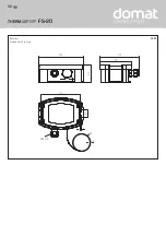
126  x  90  x  50 mm    (Tyr 2)

Cable gland:  

M 16 x 1.5 ; including strain relief, exchangeable, max. inner diameter 10.4 mm

Process connection:  

by mounting clamps 

MK- 05 - K


(included in the scope of delivery)

Electrical  connection:  

0.14  - 1.5 mm²,  via  screw  terminals

Routing:  

bending radius > 35mm  

admissible vibration load ≤ ½g 

admissible tensile load < 100 N

Permitted humidity:  

< 95 % r. H., non-precipitating air

Protection class:  

III   (according to EN 60 730)

Protection  type:  

IP 65

  (according to EN 60 529)

Standards:  

CE-conformity, electromagnetic compatibility according to EN 61 326, EMC directive 2014 ⁄ 30 ⁄ EU

Equipment:  

display with illumination, 

three-line, cutout approx. 70 x 40 mm (W x H), for displaying the actual temperature, 

measuring range overrange/underrange of the set switch point (frost protection temperature),  

and alarm indicator for "frost" or "error" (capillary breakage, overvoltage/undervoltage)

Internal diagnostics: 

Error 1

 in case of cable / capillary breakage  

Error 2

  in case of undervoltage / overvoltage 

(relay automatically switches to frost)

THERMASREG

®

  FS-20    

Two-phase frost protection thermostats

Type ⁄ WG02 

Measuring 

Range

Output

Sensor    Display 

length

Item No.

FS-20

FS20-UW LCD 3M

0...+15 °C

2 x 0 -10 V,  1 x changeover contact   

3,0 m 

9102-1012-2102-030D1

FS20-UW LCD 6M

0...+15 °C

2 x 0 -10 V,  1 x changeover contact  

6,0 m 

9102-1011-2102-030D1

FS-20 xx HE

with heating element

FS20-UW-HE LCD 3M

0...+15 °C

2 x 0 -10 V,  1 x changeover contact   

3,0 m 

9102-1012-2112-030D1

FS20-UW-HE LCD 6M

0...+15 °C

2 x 0 -10 V,  1 x changeover contact  

6,0 m 

9102-1011-2112-030D1

ACCESSORIES
KRD-04

Capillary tube gland bracket

7100-0030-7000-000

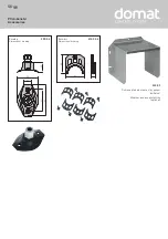
MK-05-K

Mounting clamps (6 pieces) plastic (included in the scope of delivery)

7100-0034-1000-000

WS-03

Weather and sun protection hood, 200 x 180 x 150 mm, stainless steel 

V2A

 (1.4301)

7100-0040-6000-000

Summary of Contents for THERMASREG FS-20

Page 1: ...ction thermostat with control and cascading input with active and switching output 6000 3570 0000 1XXD1 35700 2020 D1 V103 09 2020 Domat Control System s r o U Panasonicu 376 530 06 Pardubice Stare Civice CZ Česká republika Tel 420 461 100 823 Fax 420 226 013 092 info domat cz www domat int com Gratulujeme Zakoupili jste produkt německé kvality Congratulations You have bought a German quality prod...

Page 2: ...THERMASREG FS 20 G FS 20 Rozměry Dimensional drawing KL 50 126 112 4 20 M16x1 5 ø2 112 90 ...

Page 3: ...lušenství Accessories Rozměry KRD 04 Dimensional drawing Rozměry MK 05 K Dimensional drawing 50 50 11 58 20 86 60 ø5 2 25 WS 03 Ochrana před sluncem a vlivy počasí volitelně Weather and sun protection optional ...

Page 4: ...rní trubice ve vzdálenosti 20 cm od krytu Kryt 15 50 C Skladování transport 30 70 C Kryt Plast odolný vůči UV záření materiál Polyamid 30 vystužené skelnými kuličkami s rychloupínacími šrouby kombinace s drážkou hlavou Phillips Barva dopravní bílá podobná RAL 9016 Kryt displeje je průhledný Rozměry krytu 126 x 90 x 50 mm Tyr 2 Kabelová průchodka M 16 x 1 5 s odlehčením tahu vyměnitelná max vnitřní...

Page 5: ...vozní napětí 24V st ss Provozní napětí UB GND Výstup teplota 0 10V 0 15 C Řídící vstup 0 10V Kaskádový vstup 0 10V Výstup ventil 0 10V Rozpínací Přepínací 24 V Spínací Konektor displej Strana kontaktů LED Alarm Ochrana proti mrazu DIP přepínač FS 20 Reset po protimrazové ochraně režim nastavitelný DIP 1 Ruční reset manuál Alarm zůstane uložen ON Auto reset automatický Alarm je automaticky resetová...

Page 6: ...ítí a podsvícení displeje bliká Symbol FROST se objeví ve 3 řádku na levé straně displeje Měřicí rozsah podtlaku Pokud skutečná teplota klesne pod hodnotu 0 0 C zůstane v 1 řádku nezměněna Ve 2 řádku se objeví poznámka 0 C Překročení měřícího rozsahu Pokud skutečná teplota stoupne nad hodnotu 15 0 C zůstane v 1 řádku nezměněna Ve 2 řádku se objeví poznámka 15 C Alarm Chyba Pokud senzor selže v důs...

Page 7: ...oměnné SE a Frost signal V tomto případě proměnná Frost signal popisuje výstupní chování AV při SE 0 V Maximální výstupní napětí je omezeno na 10 V Prostřednictvím kaskádového vstupu KE lze navzájem spojit několik zařízení na ochranu proti mrazu aby zakryly větší průřez kanálu pro monitorování mrazu AV výstup prvního zařízení je připojen ke vstupu KE druhého zařízení Logika interního zařízení rozh...

Page 8: ...schéma FS 20 Vnitřní funkční blok FS 20 10V 0V SE KE FS 6K FS MAX 10V Ventil otevřen 0V Ventil uzavřen DDC FS 1 FS 2 FS n S E A V K E S E A V K E S E A V K E 0 100 0 10V 10V Ventil otevřen 0V Ventil uzavřen Ventil REGULÁTOR KASKÁDOVÁNÍ ...

Page 9: ...n jednocestný usměrňovač nebo ochranná dioda proti přepólování Tento vnitřní jednocestný usměrňovač také umožňuje napájet střídavým proudem i zařízení s výstupem 0 10 V Výstupní signál lze měřit měřícím přístrojem Výstupní napětí je měřeno proti nulovému potenciálu 0 V vstupního napětí Pokud je toto zařízení napájeno stejnosměrným napájecím napětím musí být pro napájení UB použito 15 36 V ss svork...

Page 10: ... se zařízením jsou bez výhrady platné Odchylky od katalogové prezentace nejsou výslovně zmíněny a jsou možné z hlediska technického pokroku a neustálého zlepšování našich produktů V případě jakýchkoli změn provedených uživatelem záruka zaniká Toto zařízení nesmí být umístěno v blízkosti zdrojů tepla nebo být vystaveno jejich vlivu Také se zcela vyhněte přímému dopadu slunečního záření nebo ozařová...

Page 11: ......

Page 12: ...be 20 60 C capillary tube at a distance of 20 cm from the housing Housing 15 50 C Storage transport 30 70 C Housing plastic UV resistant material polyamide 30 glass globe reinforced with quick locking screws slotted Phillips head combination colour traffic white similar to RAL 9016 housing cover for display is transparent Housing dimensions 126 x 90 x 50 mm Tyr 2 Cable gland M 16 x 1 5 including s...

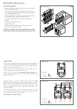
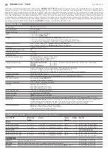
Page 13: ...D Output temperature 0 10V 0 15 C Control input 0 10V Cascading input 0 10V Output valve 0 10V NC Normally Closed COM Common changeover 24 V NO Normally Open Switching point adjustment Plug for display Contact pin side Frost protection alarm LED DIP Switches FS 20 Resetting after frost protection Mode adjustable DIP 1 Reset Hand manually Alarm remains saved ON Reset Auto automatically Alarm is res...

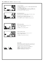
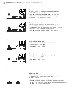
Page 14: ...ng blinks The 3rd line in the display shows the FROST symbol on the left Falling below the measuring range If the actual temperature falls below the value of 0 0 C it remains the same in the 1st line The 2nd line shows the note 0 C Exceeding the measuring range If the actual temperature exceeds the value of 15 0 C it remains the same in the 1st line The 2nd line shows the note 15 C Alarm error mes...

Page 15: ...rature falls below the set switchpoint FS 6 K the voltage output AV increases in a linear fashion from 0 V to 10 V The increase here amounts to 1 67 V for every degree Kelvin by which the temperature approaches the preset switchpoint FS The output voltage 10 V is therefore issued at FS measured temperature If you increase SE the output voltage AV is increased by this amount The AV output therefore...

Page 16: ...ctional diagram FS 20 Internal function block FS 20 10V 0V SE KE FS 6K FS MAX 10V Valve open 0V Valve closed DDC FS 1 FS 2 FS n S E A V K E S E A V K E S E A V K E 0 100 0 10V 10V Valve open 0V Valve closed Valve CONTROLLER CASCADING ...

Page 17: ...d polarity at one field device a supply voltage short circuit would be caused by that device The consequential short circuit current flowing through this field device may cause damage to it Therefore pay attention to correct wiring Circuitry Circuitry 0 10V 0V GND 0 10V 0V GND Power supply AC 24V 0V DC 15 36V GND Circuitry 0 10V 0V GND V Power supply AC 24V 0V DC 15 36V GND G Mounting and Installa...

Page 18: ...erating instructions delivered together with the device are exclusively valid Deviations from the catalogue representation are not explicitly mentioned and are possible in terms of technical progress and continuous improvement of our products In case of any modifications made by the user all warranty claims are forfeited This device must not be installed close to heat sources e g radiators or be e...

Page 19: ...zchybnou kvalitu zaručujeme v rámci našich Všeobecných obchodních podmínek Subject to errors and technical changes All statements and data herein represent our best knowledge at date of publication They are only meant to inform about our products and their application potential but do not imply any warranty as to certain product characteristics Since the devices are used under a wide range of diff...

Page 20: ... G THERMASREG FS 20 ...

Reviews: