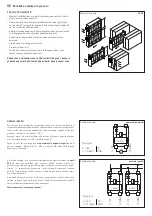
Connecting scheme
Parallel operation
Connecting scheme
Individual operation
SUPPLY VOLTAGE :
For operating voltage reverse polarity protection, a one-way rectifier or
reverse polarity protection diode is integrated in this device variant.
This internal one-way rectifier also allows operating 0 - 10 V devices on AC
supply voltage.
The output signal is to be tapped by a measuring instrument. Output
voltage is measured her against zero potential (O V) of the input voltage!
When this device is operated on
DC supply voltage
, the operating voltage
input UB+ is to be used for 15...36 V DC supply and UB – or GND for ground
wire!
When several devices are supplied by one 24 V
AC voltage supply
, it is to be
ensured that all ”positive“ operating voltage input terminals (+) of the field
devices are connected with each other and all ”negative“ operating voltage
input terminals (–) (= reference potential) are connected together (in-phase
connection of field devices). All outputs of field devices must be referenced
to the same potential!
In case of reversed polarity at one field device, a supply voltage short-
circuit would be caused by that device. The consequential short-circuit
current flowing through this field device may cause damage to it.
Therefore, pay attention to correct wiring!
Circuitry
Circuitry
0...10V
0V/GND
0...10V
0V/GND
Power supply
AC 24V~
0V
DC 15-36V = GND
Circuitry
0...10V
0V/GND
V
Power supply
AC 24V~
0V
DC 15-36V = GND
G
Mounting and Installation
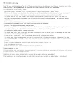
NOTES REGARDING
– Please ensure that the minimum temperature at the capillary
does not develop at the device‘s housing or at the sensors
(installed inside the housing).
– The limit value must actually be exceeded over more than
20 cm of the length of the capillary. This necessary minimum
length of 20 cm may subdivide into several sections.
– The capillary tube must not be bent several times or kinked.
This could cause leakage and the system‘s failure to function.
– Ensure not to kink or squash the sensor element
– The voltage output is short-circuit proof.
– Applying overvoltage will destroy the device.
– If this device is operated beyond the specified range,
all warranty claims are forfeited.
If the sensor element’s admissible load limits are exceeded,
ensure to use an adequate support structure.
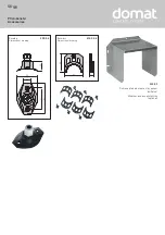
Mounting diagram
FS-20
< 1m
< 1m
< 1m

