background image

1

USA

SERVICE OFFICE

Dometic Corporation

509 South Poplar Street

Lagrange, IN 46761

260-463-4858

CANADA

Dometic Distribution

866 Langs Drive

Cambridge, Ontario

CANADA N3H 2N7

519-653-4390

For Service Center

Assistance Call:

800-544-4881

SERVICE INSTRUCTIONS

Americana

AMES/AES 2-Way

AMES/AES 3-Way

Form No. 3308740.004  11/03

©2003 Dometic Corporation

LaGrange, IN 46761

3308741.002 2-Way

3308742.000 3-Way

Universal Power Module Kit

Installation Instructions

3308741.002 2-Way Kit Includes:

3308742.000 3-Way Kit Includes:

(1)3850415013 Power Module Assembly

(1)3850415013 Power Module Assembly

(1)3308727.001 Wiring Diagram

(1)3308727.001 Wiring Diagram

(1)3308770.001 Wire, Black

(1)3308769.003 Wire Connector

(1)3308772.007 Wire Harness, 2-way

(1)3308770.001 Wire, Black

(1)3308774.003 Screw, #4 x 1/2"

(1)3308771.009 Wire, Red

PRH Self Tapping

(1)3308773.005 Wire Harness, 3-Way

(1)3308740.004 Installation Instructions

(1)3308774.003 Screw, #4 x 1/2"

PRH Self Tapping

(1)2930385006 Relay, 12VDC

(1)3308740.004 Installation Instructions

Summary of Contents for 3308741.002

Page 1: ...iversal Power Module Kit Installation Instructions 3308741 002 2 Way Kit Includes 3308742 000 3 Way Kit Includes 1 3850415013 Power Module Assembly 1 3850415013 Power Module Assembly 1 3308727 001 Wiring Diagram 1 3308727 001 Wiring Diagram 1 3308770 001 Wire Black 1 3308769 003 Wire Connector 1 3308772 007 Wire Harness 2 way 1 3308770 001 Wire Black 1 3308774 003 Screw 4 x 1 2 1 3308771 009 Wire ...

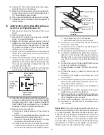
Page 2: ...a new Eyebrow Dis play the universal board self recognizes which display type it is connected to therefore the eyebrow does not have to be replaced The installer must strictly adhere to the instal lation procedure below paying specific attention to tabs J1 to J4 if not wired correctly damage to the board will result REPLACEMENT INSTRUCTIONS A 3308741 002Americana and 2 WayAMES AES Refrigerators Un...

Page 3: ...r e Close hinged top cover until latched f Reconnect battery wire to terminal block 10 Connect the 12V lead from the DC heater to terminal 87 of the relay 11 Connect the 12V lead from the DC heater to the ground terminal strip 12 Connect the red 12VDC wire to J1 terminal 13 Connect the Light Heating Cable blue wire s to either J2 or J3 terminals on the board In older re frigerators these two wires...

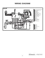
Page 4: ...TRODE RETAINER FOR BURNER H I TERMINAL BLOCK GROUND TERMINAL STRIP J K ABSORPTION UNIT HEATER 120V AC L M HEATER 12V DC LIGHT N O SWITCH FUSE 3A P Q FUSE 5A DC HEATER RELAY R S HEATING CABLE SWITCH T U TERMINAL BLOCK 1 WHITE BLACK 2 3 GREEN GREEN YELLOW 4 5 GREY BROWN 6 7 BLUE YELLOW 8 BLUE BLUE WHITE 12V DC 120V AC M L 2 9 2 2 D 7 1 K U 9 2 J 7 E R 5 F G 8 A N O I H P3 YELLOW P Q S P2 P1 GND 2 9 ...

Page 5: ...t appliances and components found on RVs was something that I always had a desire to create I hope this resource makes your RV repairs easier as it has mine but please be careful and follow proper safety practices when attempting to repair your own RV If in doubt please consult with a professional RV technician All service manuals provided on www myrvworks com are believed to be released for distr...

Reviews: