

2
These instructions must be read and under-
stood before installation of this kit. This kit
must be installed by a Dometic Service Cen-
ter or a qualified service technician. Modifi-
cation of this product can be extremely haz-
ardous and could result in personal injury or
property damage.
SAFETY INSTRUCTIONS
This manual has safety information and instruc-
tions to help users eliminate or reduce the risk
of accidents and injuries.
RECOGNIZE SAFETY INFORMATION
This is the safety-alert symbol. When you see
this symbol in this manual, be alert to the poten-
tial for personal injury.
Follow recommended precautions and safe op-
erating instructions.
UNDERSTAND SIGNAL WORDS
A signal word
,
WARNING
OR
CAUTION
is used
with the safety-alert symbol. They give the level
of risk for potential injury.
Indicates a potentially hazard-
ous situation which, if not avoided, could result
in death or serious injury.
Indicates a potentially hazard-
ous situation which, if not avoided may result in
minor or moderate injury.
When used without the safety
alert symbol indicates, a potentially hazardous
situation which, if not avoided may result in prop-
erty damage.
Read and follow all safety information and in-
structions.
!
WARNING
!
CAUTION
CAUTION
!
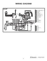
GENERAL INSTRUCTIONS
This Universal Power Module Kit is a direct replacement
for all current refrigerator control boards, namely 2 & 3 Way,
and Americana. There is no need for a new Eyebrow Dis-
play; the universal board self-recognizes which display type
it is connected to therefore the eyebrow does not have to
be replaced. The installer must strictly adhere to the instal-
lation procedure below, paying specific attention to tabs J1
to J4; if not wired correctly damage to the board will result.
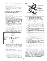
REPLACEMENT INSTRUCTIONS
A. 3308741.002 Americana and 2-Way AMES/
AES Refrigerators Universal Power Mod-
ule Kit
1. Disconnect all wires and harnesses from circuit
board.
2. Remove old circuit board.
3. Disconnect P3 harness from gas valve solenoid,
ignitor, and ground terminal.
4. Replace P3 harness with new version. Connect
white wire to one side of the gas valve solenoid,
and the yellow wire to the other side. The second-
ary yellow wire spliced to the solenoid wire con-
nects to the (+) of the ignitor.
5. Unscrew chassis ground screw from backplate and
attach black ground wire; reinsert ground screw
and firmly retighten.
6. Connect the red (+) 12VDC wire to J1 terminal.
7. Connect the Light/Heating Cable blue wire(s) to
either J2 or J3. In older refrigerators these two wires
are spliced together to one tab. In the future they
will be 2 separate wires.
8. Connect the longer of the two black Thermocouple
wires to J4 terminal.
9. Connect the positive (+) black 120 VAC Line to J5
terminal.
10. Connect the neutral (–) white 120 VAC wire to J6
terminal.
11. Connect AC Heater element wires to J7 and J8
terminals.
12. Connect remaining black Thermocouple wire to J10
terminal. This lead from the thermocouple is nor-
mally the shortest of the two.
13. Connect new black ground wire from backplate to
J9 terminal.


