background image

14

Installation

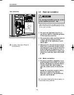
Fig. 21

Seal the installation
bays and screw them
to the vehicle roof.

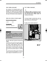
Fig. 22

Place the hood in
postion and screw it
to the installation
bays.

Measurements of roof exhaust R 500

Length

Width

Height

595 mm

205 mm

150 mm

Roof cut out:  87mm X 507 mm

Fig. 20

4.4.2 Installing roof exhaust R 500

4.4 Installing the ventilation system

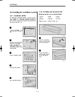
Fig. 15

Cut two rectangles in the
exterior wall of the vehi-
cle.

Fig. 16

Seal the mounting frame
making it waterproof
(

does not apply for

mounting frames with
integral seal) and screw
into position.

Fig. 17

Insert ventilation grille.

Fig. 18

Install locking slider.

Fig. 19

Lock ventilation grille.

5

4.4.1 Installation LS300

To install the ventilation grilles, cut two rectan-
gles  

width b =  490 mm, height a 249 mm

,

in the outer wall of the vehicle (for position of
the cuts, see Fig. 14).

b

a

14 x

289 0318-20_EN_RMD8xxx-Installation_N2.qxp  03.07.2012  13:07  Seite 14

Summary of Contents for ABSORPTION RMD 8501

Page 1: ...REFRIGERATION REFRIGERATORS RMD8501 RMD8505 RMD8551 RMD8555 Absorber refrigerator Installation Manual Absorber K hlschrank Montageanleitung EN DE...

Page 2: ......

Page 3: ...RMD 8501 RMD 8505 RMD 8551 RMD 8555 EN EN MBA 07 2012 N 2 English Installation instructions Absorption refrigerator for recreation vehicles...

Page 4: ...2 Dometic GmbH 2012 Subject to change without prior notice Dometic GmbH In der Steinwiese 16 D 57074 Siegen www dometic com...

Page 5: ...4 0 Installation instructions 9 4 1 Installation 9 4 1 1 Side installation 9 4 1 2 Rear installation 10 4 1 3 Draught proof installation 10 4 2 Installation recess 12 4 2 1 Installation in the recess...

Page 6: ...vation of the instructions and handling recommendations is important for dealing with the refrigerator safely and for protecting you from injury and the refrigerator from damage You must under stand w...

Page 7: ...ture fluctuations humidity 1 6 Limitation of liability 1 7 Declaration of conformity Information INFORMATION gives you supplementary and useful guidance when dealing with your refrige rator Environmen...

Page 8: ...arise through unpro fessional procedures WARNING Never use an unshielded flame to check gas bearing parts and pipes for leakage There is a danger of fire or explosion DANGER Never open the absorber c...

Page 9: ...ial number Electrical rating details Gas pressure 2 1 3 4 5 Description of model 3 0 Description of model 3 1 Model identification The rating plate is to be found on the inside of the refrigerator It...

Page 10: ...Fig 2 RMD 8xxx H W D RMD 8501 RMD 8505 RMD 8551 RMD 8555 1245x523x567 1245x523x567 1245x523x622 1245x523x622 160 lit 160 lit 190 lit 190 lit 40 kg 40 kg 41 5 kg 41 5 kg 30 lit 30 lit 35 lit 35 lit 190...

Page 11: ...t in Dometic GmbH s warranty obliga tions becoming void The appliance may be installed by autho rised personnel only WARNING Fig 4 The air vent grilles offer an unobstruc ted dissipation of heat and e...

Page 12: ...stallation method as it does not provide proper ven tilation Please refer to the description in section 4 2 CAUTION Fig 6 4 1 3 Draught proof installation Refrigerators in motorhomes caravans or other...

Page 13: ...ont Ensure that the seals abut the case evenly This installation option facilitates the removal and installation of the appliance for servicing Abb 8 Fig 7 Fig 9 1 1 2 2 Proposal 1 The cavity in betwe...

Page 14: ...level of the vehicle Fig 16 allowing unburnt gas heavier than air to escape directly into the open air The gas burner must be located above the edge 1 Fig 11 1 Fig 12 Should this arrangement prove im...

Page 15: ...turer s warranty product liability CAUTION Minimum height of ventilation H 1 Roof exhaust R500 1250 mm Lower vent grille LS300 2 Upper vent grille LS300 1400 mm Lower vent grille LS300 Fig 13 4 3 2 He...

Page 16: ...lling the ventilation system Fig 15 Cut two rectangles in the exterior wall of the vehi cle 1 Fig 16 Seal the mounting frame making it waterproof does not apply for mounting frames with integral seal...

Page 17: ...Exhaust duct system After the refrigerator is put in its final place secure the screws into the wall of the recess The screws must penetrate the casing of the refrigerator Fig 24 Fig 25 In the sidewal...

Page 18: ...Height Width Thickness 907 4 1 mm 507 5 1 mm max 1 7 mm Lower door Height Width Thickness CAUTION 3 4 2 1 Frameless decor panel Decor panel with frame Remove the lateral ledge 1 from the door ledge is...

Page 19: ...re the gas cylinder is installed The gas connection to the appliance must be installed securely and free of stress using pipe connectors and must be securely connected to the vehicle a hose connection...

Page 20: ...ance as well as any claims from warranty and product liabili ty void Specialised personnel are accredited experts who are able by virtue of their training and knowledge to vouch for the correct instal...

Page 21: ...ours perform the power supply to the 12V heating element connection A B in wiring dia gram pg 22 in a way to have the 12V supply only live while the vehicle ignition is switched on The connection C D...

Page 22: ...onnection 12 V D signal connection S signal connection Heating element mains connection 230 V AC Plug in contacts manufacturer Stocko MF 9562 002 80E MF 9562 002 8 OC 3 pin with D contact MF 9562 003...

Page 23: ...optionally achieved by mounting solar equipment to the vehicle The solar power equipment must be provided with a solar charging controller with AES output adequate charging controllers available in se...

Page 24: ...22 Installation 4 9 5 Circuit diagrams Fig 38 1 C D B A...

Page 25: ...V DC supply at the terminals C D permanent voltage supply for functional electronics 12V OUT 12 V power supply for optional connections Ground connection heating element 12VDC Positive connection heat...

Page 26: ......

Page 27: ...RMD 8501 RMD 8505 RMD 8551 RMD 8555 DE DE MBA 07 2012 N 2 Deutsch Deutsch Einbauanleitung Absorber K hlschrank f r Freizeitfahrzeuge...

Page 28: ...2 Dometic GmbH 2012 nderungen vorbehalten Dometic GmbH In der Steinwiese 16 D 57074 Siegen www dometic com...

Page 29: ...lschranks 7 3 3 Technische Daten 8 4 0 Einbauanleitung 9 4 1 Einbau 9 4 1 1 Seitlicher Einbau 9 4 1 2 Heckeinbau 10 4 1 3 Zugdichter Einbau 10 4 2 Einbaunische 12 4 2 1 Aufstellen in der Nische 11 4 3...

Page 30: ...tig und sch tzt Sie und den K hlschrank vor Sch den Das Gelesene muss verstanden worden sein bevor Sie eine Ma nahme durch f hren Bewahren Sie diese Installationsanleitung sorgf ltig auf sodass sie je...

Page 31: ...schr nkung 1 7 Konformit tserkl rung Information INFORMATION gibt Ihnen erg nzende und n tzliche Hinweise zum Umgang mit Ihrem K hlschrank Umwelthinweis UMWELTHINWEIS gibt Ihnen n tzliche Hinweise zur...

Page 32: ...d oder Personensch den entstehen WARNUNG berpr fen Sie niemals gasf hrende Teile und Leitungen mit einer offenen Flam me auf Undichtigkeit Es besteht Brand oder Explosionsgefahr GEFAHR ffnen Sie niema...

Page 33: ...n Sie bei allen Kontakten mit dem Kundendienst oder der Ersatzteilbestellung 3 2 Typenschild des K hl schranks RM 8 5 0 1 1 5 D Refrigerator Mobile Mobiler Absorberk hlschrank Modellreihe 5 Breite 523...

Page 34: ...RMD 8501 RMD 8505 RMD 8551 RMD 8555 1245x523x567 1245x523x567 1245x523x622 1245x523x622 160 lit 160 lit 190 lit 190 lit 40 kg 40 kg 41 5 kg 41 5 kg 30 lit 30 lit 35 lit 35 lit 190 W 170 W 190 W 170 W...

Page 35: ...K hlleistung bei hohen Umgebungstemperaturen zu erreichen Abb 3 Abb 4 L ftungsgitter frei OK 4 0 Einbauanleitung Das Ger t und die Abgasf hrung m ssen grunds tzlich so eingebaut werden dass es f r Ser...

Page 36: ...e und Entl ftung wie unter Punkt 4 2 beschrieben nicht gew hrlei stet ist VORSICHT 4 1 3 Zugdichter Einbau K hlger te in Wohnwagen Reisemobilen oder sonstigen Fahrzeugen m ssen zugdicht ein gebaut sei...

Page 37: ...s die Dichtungen gleichm ig am Geh use anliegen Der Ausbau des K hlschranks zur Wartung und Reparatur ist so leicht m glich Abb 8 Abb 7 Abb 9 1 1 2 2 Vorschlag 1 Der Raum der sich zwischen Fahrzeugaus...

Page 38: ...ischenboden ange ordnet sein Abb 16 damit unverbranntes Gas schwerer als Luft auf direktem Weg ins Freie gelangt Der Gasbrenner muss sich oberhalb der Kante 1 befinden Wenn diese Anordnung nicht m gli...

Page 39: ...diesen Zweck gepr ft und zugelassen ist Installation mit Dachentl fter R500 und unterem L ftungsgitter LS300 Installation mit oberem und unterem L ftungsgitter LS300 1 Dachentl fter R500 1250 mm Unte...

Page 40: ...L ftungssysteme Abb 15 Rahmenausschnitt in Au enwand herstellen 1 Abb 16 Einbaurahmen wasser undurchl ssig abdichten entf llt beim Einbau rahmen mit integrierter Dichtung und fest schrauben 2 Abb 17...

Page 41: ...seine endg ltige Lage gebracht ist werden die Schrauben durch das Geh use des K hlschrankes in die Nischenwand geschraubt Abb 24 Abb 25 In den Seitenw nden des K hlschrankes sind vier Kunststoffbuchs...

Page 42: ...4 1 mm 507 5 1 mm max 1 7 mm Untere T re H he Breite Dicke VORSICHT 3 4 2 1 Rahmenlose Dekorplatte Dekorplatte mit Rahmen Ziehen Sie die seitliche Leiste 1 der T r ab Leiste ist aufgesteckt nicht ver...

Page 43: ...9 siehe Abb 34 Nach fachgerechter Installation ist eine Dichtheitspr fung und eine Flammprobe Autorisierte Fachkr fte sind anerkannte Sachkundige dieaufgrund ihrer Ausbildung und Kenntnisse die Gew hr...

Page 44: ...ew hrleistung und Produkthaftung Autorisierte Fachkr fte sind anerkannte Sachkundige die aufgrund ihrer Ausbildung und Kenntnisse die Gew hr daf r bieten dass die Installation ordnungs gem durchgef hr...

Page 45: ...die Stromversorgung f r die Heizpatrone Anschluss A B im Schaltschema ab S 22 so auszuf hren dass sie beim Umdrehen des Z ndschl ssels unter brochen wird An dem Anschluss C D Beleuchtung Elektronik An...

Page 46: ...Heizelement 12V Anschluss Elektronik 12V Anschluss D Signal Anschluss S Signal Heizelement Netz 230V 2 3 4 1 Steckkontakte Hersteller Stocko MF 9562 002 80E MF 9562 002 8 OC 3 polig mit D Kontakt MF...

Page 47: ...Anschluss Alternativ kann die Energieart 12V DC ber eine fahrzeugeigene Solaranlage eingespeist werden Die Solaranlage muss ber einen Solarladeregler mit AES Ausgang verf gen entsprechende Laderegler...

Page 48: ...22 Einbau Abb 38 4 9 5 Schaltschema 1 C D B A...

Page 49: ...lich eine 12V DC Dauerversorgung an den Klem men C D anzuschlie en Dauerversorgung f r die Funktionselektronik 12V OUT 12V Versorgung f r optionale Anschl sse Masse Heizelement 12V Plus Heizelement 12...

Page 50: ......

Page 51: ......

Page 52: ...90 64 9 622 1573 Mail customerservices dometic co nz NORWAY Dometic Norway AS ster yveien 46 N 3232 Sandefjord 47 33428450 47 33428459 Mail firmapost dometic no POLAND Dometic Poland Sp z o o Ul Pu aw...

Reviews: