background image

9

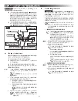
There is a 2 minute rest period be-

tween each attempt.

III.  If ignition cycle fails, upper compartment 

remains OFF, and will not cool.

To attempt a new ignition cycle for 

LP gas operation, see “A. Purge LP 

Gas Lines” on page (10).

3. 

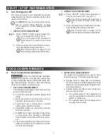
LOWER FOOD COMPARTMENT

The lower food compartment (drawer) operates 

on electric power only. The power source is au-

tomatically selected in the following order:

a.  120 Vac - [default].

The lower compartment attempts to operate 

on 120 Vac power first.

120 Vac is 

ALWAYS 

the primary 

source of power. The lower compart-

ment reverts back to 120 Vac (from 12 

Vdc) whenever it becomes available.

b.  12 Vdc - [secondary].

The lower compartment automatically 

switches to 12 Vdc power if 120 Vac is un-

available.

If 120 Vac becomes available during 

12 Vdc operation, the lower compart-

ment automatically switches back to 

120 Vac power.

C.  Temperature (Thermostat) Control

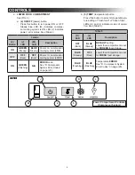
See “A. Control Panel Buttons” on page 

(7) for details on control settings and LED 

indicators.

1. 

UPPER FOOD COMPARTMENT

The upper food compartment has (3) tempera-

ture modes (settings):

a.  Cold (minimum cooling level).
b.  Colder (intermediate cooling level).

c.  Coldest (maximum cooling level).

2. 

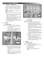
LOWER FOOD COMPARTMENT

The lower food compartment has (2) tempera-

ture modes (settings):

a.  Frozen food (freezer) mode - [default].
b.  Fresh food (refrigerator) mode.

 

Before changing temperature 

setting from fresh food to freezer, make sure 

interior surfaces are completely dry. Other-

wise, drawer slides may freeze up, making 

drawer operation difficult.

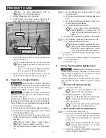
B.  Modes Of Operation

See “A. Control Panel Buttons” on page 

(7) for details on control settings and LED 

indicators.

1. 

STANDBY MODE

If refrigerator controls cannot read food com-

partment temperature, or if temperature is out-

side normal operating range, the affected sys-

tem switches to standby mode. The refrigerator 

continues to operate using any available energy 

source.
Standby mode for upper food compartment runs 

the absorption system continuously. This could 

cause fresh food items to freeze.
Standby mode for lower food compartment runs 

the compressor system on an intermittent cycle. 

This could cause frozen food items to thaw, or 

fresh food items to freeze.
For either incident, the affected cooling system 

remains in standby mode until sensor failure is 

repaired and system is reset.

2. 

UPPER FOOD COMPARTMENT

The upper food compartment operates on (2) 

power modes:

a.  Auto mode - [default].

In this mode, the power source is automati-

cally selected in the following order:

I.  120 Vac - [default].

Electric power takes priority in this mode. 

The upper compartment attempts to op-

erate on electric power first.

Electric power is 

ALWAYS 

the pri-

mary source of power. The upper 

compartment reverts back to elec-

tric power (from other power sourc-

es) whenever it becomes available.

II.  LP Gas - [secondary].

The upper compartment automatically 

switches to LP gas if electric power is un-

available.

If electric power becomes available 

during LP gas operation, the upper 

compartment automatically switch-

es back to electric power.

b.  LP gas mode.

In this mode, the upper compartment only 

operates on LP gas. The ignition cycle pro-

ceeds to light the LP gas burner in the fol-

lowing order:

I.  The lighter sparks for approximately 45 

seconds.

II. 

If first attempt fails, the lighter repeats up 

to 3 times.

CONTROLS

Summary of Contents for DMH1072

Page 1: ...Open windows 2 Do not attempt to light appliance 3 Do not touch electrical switches 4 Extinguish any open flame 5 Shut off fuel supply 6 Evacuate immediately and call emergency services Failure to fol...

Page 2: ...idelines 11 B Shelving 12 C Baskets 12 D Lower Food Compartment Drawer 13 PRODUCT CARE 13 A Defrost Food Compartment s 13 B Clean Food Compartment s 14 C Airing Position Store Refrigerator 14 PRODUCT...

Page 3: ...nal Vehicles CSAZ240 4 Gas Equipped Recreational Vehicles and Mobile Housing CSA B149 1 Natural Gas and Propane Installation Code This manual has safety information and instructions to help you elimin...

Page 4: ...T be installed serviced by a qualified service technician Do NOT modify this product in any way Modifica tion can be extremely hazardous Disconnect product from power supply if ap plicable and do NOT...

Page 5: ...ing on model Quantity and position of items may also vary See FIG 1 FIG 1 Upper Food Storage Compartment Lower Food Storage Compartment Door Drawer LH Light Airing Slide RH Light Airing Slide Milk She...

Page 6: ...infor mation on absorption cooling systems and consequences of exposure to refrigerant The upper food compartment is used for fresh food storage only This compartment is cooled by vapor absorption ref...

Page 7: ...s LP gas ignition sta tus See Table 2 Table 2 B LED C LED D LED Description GREEN Steady OFF Dark OFF Dark Absorption cooling systemisinAUTOMATIC detect mode OFF Dark GREEN Steady OFF Dark Absorptionc...

Page 8: ...mperature ERROR See D Compressor System Error Codes on page 20 2 LOWER FOOD COMPARTMENT See FIG 3 a 4 ON OFF power button Press this button to turn power ON or OFF Steady blue LED M indicates compres...

Page 9: ...ns on page 7 for details on control settings and LED indicators 1 STANDBY MODE If refrigerator controls cannot read food com partment temperature or if temperature is out side normal operating range t...

Page 10: ...g warnings could result in death or serious injury FIRE OR EXPLOSION HAZARD BEFORE refu eling or parking near a gasoline pump make sure ALL LP gas appliances vented to the outside of RV are shut OFF O...

Page 11: ...oline soaked rags or other flammable vapors and liquids inside stor age compartment s Failure to obey this warning could result in death or serious injury 1 ALL FOOD COMPARTMENTS The following points...

Page 12: ...ight side disengage from refrigerator wall indents II Tilt right side of shelf at an angle up or down III Slide shelf to the right until shelf bushings left side disengage from refrigerator wall inden...

Page 13: ...sh lever upward See FIG 8 c Locate lever on right side drawer slide and push lever downward d Pull drawer forward removing from refrig erator FOOD COMPARTMENTS PRODUCT CARE A Defrost Food Compartment...

Page 14: ...ith baking soda solu tion c Wipe down surfaces with warm water to re move baking soda solution d Dry surfaces with clean cloth To clean lower food compartment drawer MUST be removed See D Lower Food C...

Page 15: ...n On products built after June 2016 the 3 amp fuse for the absorption control system is a resettable fuse and can NOT be replaced If the resettable fuse has been tripped determine and remedy the cause...

Page 16: ...ator enclosure 3 Disconnect the positive 12 Vdc terminal from supply battery 4 Turn manual shutoff valve OFF to closed posi tion See FIG 4 The slot on manual shutoff valve is vertical when valve is of...

Page 17: ...2 FIRE OR EXPLOSION HAZ ARD NEVER use an open flame to check for gas leaks Failure to obey this warning could re sult in death or serious injury Apply an approved non corrosive leak detection solutio...

Page 18: ...ser habits including fre quent or prolonged opening of food compartment s Do not open drawer door longer than necessary Regular defrosting is required See A Defrost Food Compartment s on page 13 Drawe...

Page 19: ...page 6 Over packed food storage Arrange food to allow free air circulation Extremely cold subzero weather conditions Turn upper food compartment OFF When ambient temperature rises please restart uppe...

Page 20: ...is outside normal operating range Check battery Lower compartment shuts down under this condition if 120 Vac power is also NOT available 2 Compressor fan overload Foreign object s may be obstructing...

Page 21: ...02011 Lock Clip Shelf 3313470 153 Basket Freezer Wire 3313470 154 Drawer Catch Lock 3313470 152 Handle Assembly Door 3313470 151 Handle Assembly Drawer 3313470 078 Door Assembly 3313470 079 Drawer Fro...

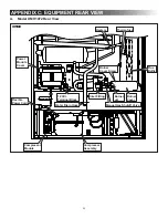
Page 22: ...ear View 12V DC FIG 15 Burner Cover Burner Jet Manual Gas Shutoff Valve Water Drain Hose Burner Cover Screw Thermofuse Flue Baffle Heaters Inlet Fitting 12 Vdc Terminal Block Power Module Cover Flexib...

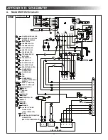
Page 23: ...5 7 25 1 6 7 86 1 5 2 5 4 2 9 3 1 2 0 5 3 5 4 3 0 1 21752 5 2035 6625 3 3 3 3 3 3 3 3 3 3 3 1 63 2 5 1 3 7 7 5 9 5 0 7 5 7 50 1 2 6 7 1 66 6 1 1 2035 6625 21752 17 5 63 6 7 86 1 3 3 1 21752 02 8 3 625...

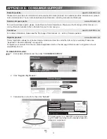
Page 24: ...istration card on the last page of this manual or register on line at www eDometic com TO REGISTER ON LINE 1 Access www eDometic com then click CONSUMER CENTER 2 Click Register My Product 3 Complete t...

Page 25: ...to keep the warranty in effect Failure of the Original Purchaser in providing this annual maintenance may void the warranty The preventative maintenance must be performed at a Dometic Authorized Servi...

Page 26: ...le Reading 25 35 Millivolts Delay Between Modes Approx 5 seconds ICE MAKER MODELS Inspect Water Valve and All Connections Yes No Inspect Heat Tape Switch for Proper Operation Yes No SECOND YEAR Date D...

Page 27: ...ur Dometic products with one of the most comprehensive warranties in the industry Please complete and mail this registration card or register your product on line at www eDometic com TIME DATED MATERI...

Page 28: ...0 days to ensure your WARRANTY VERIFICATION FACTORY COMMUNICATION OWNER CONFIRMATION 2 PLUS 3 SERVICE CONTRACT INVITATION WARRANTY VERIFICATION Your prompt registration records your right to protectio...

Reviews: