21
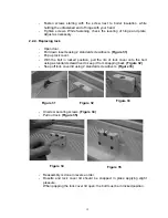
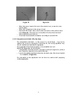
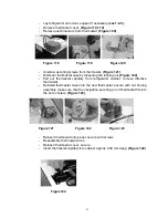
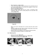
- Place the sensor head in the nest of the sensor cover, screw the cover
back in place.
- Place the 2 plugs back in the bores of cover.
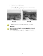
- Push back the sensor wires onto the flat connectors of the printed circuit
board
(Sensor)
. The sensor is not sensible to the two wires reversed.
- Screw electrical cover back on.
- Check electrical insulation resistance according to section
2.3.3
.
2.3.5. Temperature controller (Thermo fuse)
The temperature controller – in the event of a circuit break – may not be
replaced as a service component. If switched off, the cooling appliance may
only be repaired by replacing the aggregate.
The aggregate for servicing purposes is only available as a set.
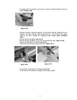
Beside the aggregate, the set includes:
- 1 temperature controller with the necessary maximum length wire, without
the connection element on the ends of the wire.
- 1 set of all available electrical connection elements, also the screws needed
for installation.
(Figure 89)
The description of the application can be found in section
2.4.1
(replacing
cooling aggregate).
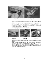
Figure 79
Figure 80

