10
B. GAS MODE
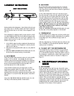
When operating in the GAS mode, the AUTO mode
indicator lamp (B) will be off and the GAS mode indica-
tor lamp (C) will be illuminated. This mode provides LP
gas operation only. The control system will activate the
ignition system and will attempt to light the burner for a
period of approximately 45 seconds. If unsuccessful,
the CHECK indicator lamp (D) will illuminate and the
GAS mode indicator lamp (C) will turn off.
To restart GAS operation, press the main power ON/
OFF button (1) to the OFF and then ON position. The
control system will attempt a new 45 second ignition
sequence.
If the refrigerator has not been used for a long time or
the LP tanks have just been refilled, air may be trapped
in the supply lines. To purge the air from the lines may
require resetting the main power ON/OFF button (1)
three or four times. If repeated attempts fail to start the
LP gas operation, check to make sure that the LP gas
supply tanks are not empty and all manual shutoff
valves in the lines are open. If the problem is still not
corrected, contact a service center for assistance.
If the control is switched to AC operation while the
CHECK indicator lamp is on, it will function properly, but
the CHECK indicator lamp will not go off until the main
power ON/OFF button is pressed to the OFF then ON
position.
C. STANDBY MODE OF OPERATION
This control system contains a feature where it will
continue to operate the cooling system in the event of a
failure of a major operating component. Two different
modes of operation can occur in this category.
If for some reason the display module becomes non-
functional, the control system will revert to full automatic
operation selecting the best energy source available
with AC as first priority, and GAS as the second priority.
The temperature of the refrigerator will be maintained at
the MID position within normal temperature tolerances.
The power module will continually attempt to
re-establish operation of the display module.
The second standby mode of operation will execute
when a failure of the temperature sensing device or
associated electronic circuitry occurs. If this should
occur, the control system will operate on the energy
source selected via the control panel. The cooling unit
will run continuously on the selected energy source. The
refrigerator will continue to operate in this mode indefi-
nitely or until a new sensor is installed and the system is
reset.
5.
5.
5.
5.
5. HO
HO
HO
HO
HOW
W
W
W
W T
T
T
T
TO USE
O USE
O USE
O USE
O USE THE REFRIGERA
THE REFRIGERA
THE REFRIGERA
THE REFRIGERA
THE REFRIGERAT
T
T
T
TOR
OR
OR
OR
OR
A.
A.
A.
A.
A. FOOD STORAGE COMPARTMENT
FOOD STORAGE COMPARTMENT
FOOD STORAGE COMPARTMENT
FOOD STORAGE COMPARTMENT
FOOD STORAGE COMPARTMENT
The food storage compartment is completely closed and
unventilated, which is necessary to maintain the required
low temperature for food storage. Consequently, foods
having a strong odor or those that absorb odors easily
should be covered. Vegetables, salads, etc. should be
covered to retain their crispness. The coldest positions in
the refrigerator are under the cooling fins and at the bottom
of the refrigerator. The warmer areas are on the upper door
shelves. This should be considered when placing different
types of food in the refrigerator.
B.
B.
B.
B.
B. FROZEN FOOD STORAGE
FROZEN FOOD STORAGE
FROZEN FOOD STORAGE
FROZEN FOOD STORAGE
FROZEN FOOD STORAGE
COMPARTMENT
COMPARTMENT
COMPARTMENT
COMPARTMENT
COMPARTMENT
Quick frozen soft fruits and ice cream should be placed in
the coldest part of the compartment which is on or just
below the freezer shelf. Frozen vegetables, may be stored
in any part of the compartment.
This compartment is not designed for deep or quick
freezing of food. Meat or fish, whether raw or prepared,
can be stored in the frozen food storage compartment
provided they are precooled first in the refrigerator. They
can be stored about three times longer in the frozen food
compartment as compared to the fresh food compartment.
To prevent food from drying out, keep it in covered dishes,
containers, plastic bags or wrapped in aluminum foil.
C.
C.
C.
C.
C.
ICE MAKING
ICE MAKING
ICE MAKING
ICE MAKING
ICE MAKING
Ice cubes can be made in the ice tray placed in the freezer
compartment. The tray should be filled with water to within
1/4" (5mm) from the top. For faster ice making, the tray
should be placed in direct contact with the freezer shelf.
To release the ice cubes, seize the tray with both hands
and twist the tray. Cubes not required should be replaced
in the tray. Refill the tray with water and replace the tray on
the freezer shelf.
Ice will be made more rapidly if the thermostat is set at its
highest position. It is a good idea to do this a few hours
before the anticipated need for ice, but be sure to move the
thermostat back to normal setting, usually about mid-
setting when the ice is formed. Food in the lower compart-
ment may be frozen if the setting is left on "COLDEST"
position.
D.
D.
D.
D.
D.
DEFROSTING
DEFROSTING
DEFROSTING
DEFROSTING
DEFROSTING
Shut off the refrigerator by pressing the main power ON/
OFF button to the UP (OFF) position. Empty the refrigera-
tor, leaving the drip tray under the finned evaporator, and
the cabinet and freezer doors open. Defrosting time can be
reduced by filling the ice tray with hot water and placing it
on the freezer shelf.

