6
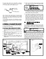
The gas supply system must incorporate a pressure
regulator to maintain a supply pressure of not more than
13-1/2 inches water column, (static) no load.
When testing the gas supply system at pressures less
than or equal to 1/2 psig, the appliance must be isolated
from the gas supply piping by closing its individual manual
shutoff valve.
In case detailed instructions on the installation and con-
nection to the gas supply are required, contact your dealer
or distributor.
9.
9.
9.
9.
9. TESTING LP GAS SAFETY SHUT
TESTING LP GAS SAFETY SHUT
TESTING LP GAS SAFETY SHUT
TESTING LP GAS SAFETY SHUT
TESTING LP GAS SAFETY SHUTOFF
OFF
OFF
OFF
OFF
The gas safety shutoff must be tested after the refrigerator
is connected to LP gas supply.
To test the gas safety shutoff, proceed as follows:
To test the gas safety shutoff, proceed as follows:
To test the gas safety shutoff, proceed as follows:
To test the gas safety shutoff, proceed as follows:
To test the gas safety shutoff, proceed as follows:
A. Start the refrigerator according to the instructions, and
switch to gas mode. See "
Section C. Operation Instruc-
tions
."
B. Check that the gas flame is lit and the gas mode
indicator lamp (C) is on. See FIG. 15.
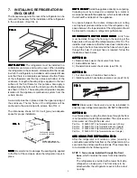
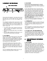
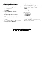
C. Close the manual shutoff valve at the back of the
refrigerator. (See FIG. 12)
D. Wait for one minute. The check indicator lamp (D)
should now be lit and the gas mode indicator lamp
should be off.
E. Remove cover (see FIG. 12) and open the manual gas
valve. Apply a noncorrosive commercial bubble solution
to burner jet (see FIG. 12).
DO NOT USE A FLAME
DO NOT USE A FLAME
DO NOT USE A FLAME
DO NOT USE A FLAME
DO NOT USE A FLAME
TO CHECK FOR GAS LEAKS.
TO CHECK FOR GAS LEAKS.
TO CHECK FOR GAS LEAKS.
TO CHECK FOR GAS LEAKS.
TO CHECK FOR GAS LEAKS.
F. No bubbles should appear at the opening of the burner
jet. The presence of bubbles indicates a defective gas
safety shutoff, and service is required.
PRESSURE
REGULATOR
LP GAS
CYLINDER
TO
REFRIGERATOR
G. If no bubbles were present at the burner jet, the gas
safety valve is working properly. Rinse jet thoroughly
with fresh water before proceeding. Be careful not to
damage burner jet. Replace cover and turn the main
switch OFF and back ON. (See "
Section C. Operation
Instructions, Item 2. Control Panel
"). Normal operation
of the burner should return. Allow the burner to operate
for a minimum of 5 minutes.
10.
10.
10.
10.
10. 120
120
120
120
120 V
V
V
V
VOL
OL
OL
OL
OLT A
T A
T A
T A
T AC ELECTRICAL
C ELECTRICAL
C ELECTRICAL
C ELECTRICAL
C ELECTRICAL
CONNECTION
CONNECTION
CONNECTION
CONNECTION
CONNECTION
The refrigerator is equipped with a three-prong (grounded)
plug for protection against shock hazards, and should be
plugged directly into a properly grounded three-prong
receptacle.
DO NOT cut or remove the grounding prong from this
DO NOT cut or remove the grounding prong from this
DO NOT cut or remove the grounding prong from this
DO NOT cut or remove the grounding prong from this
DO NOT cut or remove the grounding prong from this
plug.
plug.
plug.
plug.
plug.
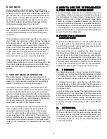
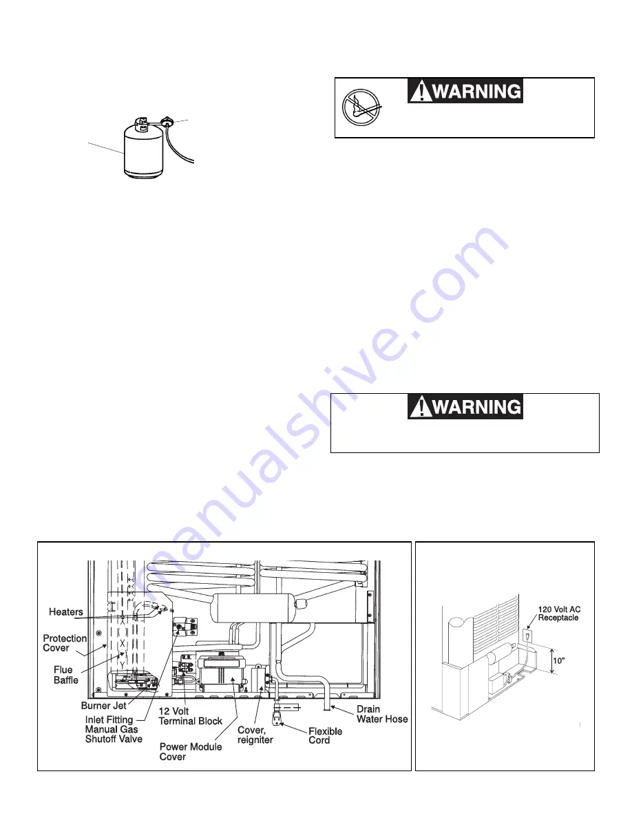
The power cord should be routed to avoid direct contact
with the burner cover, flue cover or manual gas shutoff
valve knob. The free length of the cord is 2 feet and
therefore recommended that the receptacle be located to
the right side of the refrigerator (viewed from the rear) and
approximately 10 inches from the floor (see FIG. 13).
FIG. 12
FIG. 13

