background image

9

DESCRIPTION OF OPERATING
MODES

LIMP MODE OF OPERATION

This control system contains a feature where it will con-
tinue to operate the cooling system in the event of a fail-
ure of a major operating component. Two different modes
of operation can occur in this category.

If for some reason the display module becomes non func-
tional, the refrigerator will continue to operate and the
temperature of the refrigerator will be maintained at the
MID position within normal temperature tolerances. The
power module will continually attempt to reestablish op-
eration of the display module.

The second limp mode of operation will execute when a
failure of the temperature sensing device or associated
electronic circuitry occurs. If this should occur, the re-
frigerator will run continuously.
The refrigerator will continue to operate in this mode in-
definitely or until a new sensor is installed and the sys-
tem is reset.

START UP INSTRUCTIONS

A. A continuous 12 volt DC supply must be available for

the electronic control to function.

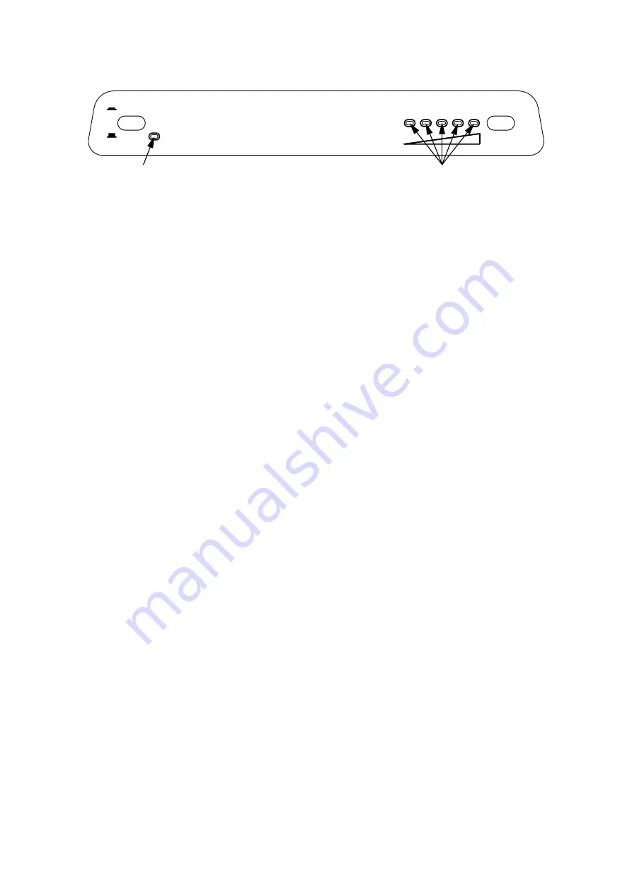
B. Press the main power ON/OFF button (1) to the

DOWN position.

C. Press the TEMPERATURE SELECTOR button (2)

until the lamp at the desired setting is illuminated.

Note: Depending on ambient temperature, if the set-
ting is left on in “COLDEST” position too long it may
cause overfreezing.

TO SHUT OFF THE REFRIGERATOR

To shut off the refrigerator press the main power ON/
OFF button (1) to the UP (OFF) position.
This shuts off all DC power to the refrigerator, including
the interior light.

DISPLAY PANEL

B

A

2

AC

OFF

ON

COLD 1

2

3

4

5

COLDEST

1

Summary of Contents for NDE1292

Page 1: ...y of this or any other appliance WARNING Improper installation adjustment alteration service or maintenance can cause injury or property damage Refer to this manual For assistance or additional inform...

Page 2: ......

Page 3: ...e Protection cover Power module and fuses Heaters Refrigerator control panel FIG 2 AC OFF ON COLD 1 2 3 4 5 COLDEST 1 2 B A C D LEGEND 1 Main Power Button ON OFF 2 Temperature Selector Button A AC Ind...

Page 4: ...ize openings The flow of ventilating air must not be obstructed The lower side vent is fitted with a panel which provides an adequate access opening for ready serviceability of the refrigerator This s...

Page 5: ...xtends at least full width and depth of the appliance Caution Use care when installing the refrigerator This refrigerator is equipped with the latest vacuum insulated panel technology These insulating...

Page 6: ...the panel Failure to follow the sequence in securing refrigerator in enclosure can cause leakage between the frame and cabinet Any space between the counter storage area or ceiling and top of the ref...

Page 7: ...ondenser coil at the back of the refrigerator VENTILATION HEIGHTS CLEARANCES Minimum clearances in inches to combustible materials are G Top 0 K Side 0 L Bottom 0 M Rear 0 N See NOTE Clearance N below...

Page 8: ...f hydrogen and ammonia gas or in severe cases completely block it resulting in a loss of cooling Any time the vehicle is parked for several hours with the refrigerator operating the vehicle should be...

Page 9: ...e or associated electronic circuitry occurs If this should occur the re frigerator will run continuously The refrigerator will continue to operate in this mode in definitely or until a new sensor is i...

Page 10: ...he refrigerator by pressing the main power ON OFF button to the UP OFF position Empty the refrigerator leaving the drip tray under the finned evaporator and the cabinet and freezer doors open Filling...

Page 11: ...r the refrig erator control system and one for the AC heater See table below To replace fuse s proceed as follows 1 Disconnect the wall plug and the 12 volt wires 2 Remove the power module cover See F...

Page 12: ...ose given in the Table on this page and the instructions are read thoroughly When mounting the panel proceed as follows See figure page 13 A Open the door 90 degrees On new refrigerators the decoratio...

Page 13: ...03633 XXX Roof Cover 3103634 XXX Lower Side Vent 3109349 XXX Power Vent Asm 3108705 744 Fill in XXX with color code numbers For color codes contact your supplier Alternate instructions forwarded with...

Page 14: ...side at the desired position Slide the wire shelf to the left The right hand side of the shelf will come loose Slide the shelf into the holes on the right hand side Lower the right hand side of the wi...

Page 15: ...15...

Page 16: ...16 MO FO 0424...

Reviews: