background image

INSTALLATION AND

OPERATING INSTRUCTIONS

REFRIGERATOR FOR LP-GAS AND ELECTRIC OPERATION

NDR 1402

USA

Corporate Office

CANADA

Service Office

2320 Industrial Parkway Elkhart, IN 46515

Dometic Distribution Inc.

Dometic Corporation

866 Langs Drive

509 South Poplar Street

Cambridge, Ontario

LaGrange, IN 46761

For Service Center Assistance

N3H 2N7 Canada

Phone: 260-463-4858

Call: 800-544-4881

Phone: 519-653-4390

825 12 23-00

®

®

Contents:

Page

Installation

4

Operating Instructions

8

Maintenance & Service

12

FOR YOUR SAFETY

If you smell gas:

1. Open windows.

2. Don’t touch electrical switches.

3. Extinguish any open flame.

4. Immediately call your gas supplier.

FOR YOUR SAFETY

Do not store or use gasoline or other

flammable vapors and liquids in the

vicinity of this or any other appliance.

WARNING: Improper installation,

adjustment, alteration, service or

maintenance can cause injury or

property damage. Refer to this

manual. For assistance or additional

information consult a qualified

installer, service agency or the gas

supplier.

Pour votre sécurité

Si vous sentez une odeur de gaz:

1. Ouvrez les fenêtres.

2. Ne touchez à aucun interrupteur.

3. Éteignez toute flamme nue.

4. Avertissez immédiatement votre fournis-

seur de gaz.

Pour votre sécurité

Ne pas entreposer ni utiliser de l’essence ni

d’autres vapeurs ou liquides inflammables à

proximité de cet appareil ou de tout autre

appareil.

Avertissement: Une installation, un réglage,

une modification, une réparation ou un

entretien non conforme aux normes peut

entraîner des blessures ou des dommages

matériels. Lisez attentivement le mode d’em-

ploi fourni avec l’appareil. Pour obtenir de

l’aide ou des renseignements supplémentai-

res, consultez un installateur ou un service

d’entretien qualifié ou le fournisseur de gaz.

All manuals and user guides at all-guides.com

all-guides.com

Summary of Contents for NDR 1402

Page 1: ...adjustment alteration service or maintenance can cause injury or property damage Refer to this manual For assistance or additional information consult a qualified installer service agency or the gas...

Page 2: ...All manuals and user guides at all guides com...

Page 3: ...re Selector Button A AC Mode Indicator Lamp B AES AUTO Mode Indicator Lamp C GAS Mode Indicator Lamp D CHECK Indicator Lamp E Temperature Indicator Lamps FIG 1 12V DC Heaters Power module and fuses Pr...

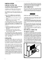
Page 4: ...the refrigerator compartment must be provided for ventilation of heavier than air fuel gases The lower vent of the recommended kits is provided with proper size openings The flow of combustion and ven...

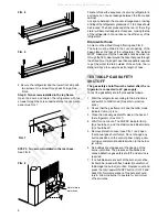
Page 5: ...is a complete seal between the front frame of the refrigerator and the top sides and bottom of the enclosure A length of sealing strip is ap plied to the rear surface of the front frame for this pur p...

Page 6: ...HUTOFF The gas safety shutoff must be tested after the re frigerator is connected to LP gas supply To test the gas safety shutoff proceed as follows 1 Start the refrigerator according to the instructi...

Page 7: ...of the refrigerator VENTILATION HEIGHTS CLEARANCES Minimum clearances in inches to combustible materials are G Top 0 K Side 0 L Bottom 0 M Rear 0 N See NOTE Clearance N below NOTE Clearance M is betw...

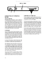
Page 8: ...eveling is not critical as the rolling and pitching movement of the vehicle will pass to either side of level keeping the liquid ammonia from accumulating in the evaporator tubing OPERATION Before sta...

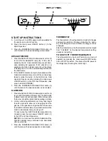
Page 9: ...y switched to the GAS mode 2 If the CHECK indicator lamp D illuminates and the GAS mode indicator lamp C is off the controls have failed to ignite the burner in the GAS mode GAS operation may be reset...

Page 10: ...mes If repeated attempts fail to start the LP gas operation check to make sure that the LP gas supply tanks are not empty and all manual shutoff valves in the lines are open If the problem is still no...

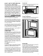
Page 11: ...f the compartment This compartment is not designed for deep or quick freezing of food Meat or fish whether raw or prepared can be stored in the frozen food storage compartment provided they are precoo...

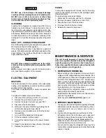
Page 12: ...ove the protection cover see FIG 1 3 Remove the power module cover see FIG 1 4 Disconnect the heater leads 5 With a pair of pliers unfold the lug holding the lid of the boiler casing and open the lid...

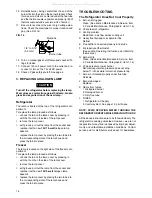
Page 13: ...r pin when cleaning the burner jet as damage can occur to the precision opening This can cause damage to the refrigerator or create a fire hazard FIG 13 Clear blue color of flame GAS EQUIPMENT ASSEMBL...

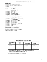
Page 14: ...e refrigerator is quality guaranteed However we are not responsible for any failures caused by improper adjust ments and unfavorable installation conditions Contact service point or distributor servic...

Page 15: ...Heater 120V 420W 2x 60V 210W 95 50 01 67 2 Burner pipe cpl 200 74 19 33 2 Jet No 76 293 11 32 02 7 Spark ignition device 293 27 81 02 0 Electrode with conductor 293 18 26 02 4 Thermocouple 385 04 52 0...

Page 16: ...r the right hand side of the wire shelf and let the left hand side slide out of the holes in the wall Slide the plastic plugs into the holes of the wall Snap the shelf locks onto the wire shelf Slide...

Page 17: ...17 All manuals and user guides at all guides com...

Page 18: ...18 All manuals and user guides at all guides com...

Page 19: ...19 All manuals and user guides at all guides com...

Page 20: ...20 MO FO 0305 All manuals and user guides at all guides com...

Reviews: