background image

5

INSTALLATION

VENTILATION

The installation shall be made in such a manner as to
provide necessary air circulation over the cooling unit.
Openings for air supply shall have a minimum dimen-
sion of not less than 1/4 inch.

Proper installation requires one lower fresh air intake
and one upper exhaust vent. The ventilation kits shown
in this instruction manual have been certified for use with
the refrigerator models listed in the table. For “Certified
Vent System Kits”
 see page 18.
The ventilation kits must be installed and used without
modification. The lower vent of the recommended kits is
provided with proper size openings.
The flow of ventilating air must not be obstructed.
The lower side vent is fitted with a panel, which provides
an adequate access opening for ready serviceability of
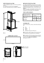
the refrigerator. This should be centered on the back of
the refrigerator.

ELECTRICAL CONNECTION

120 Volts AC Connection

The refrigerator is equipped with a three-prong (ground-
ing) plug for your protection against shock hazards and
should be plugged directly into a properly grounded three-
prong receptacle. DO NOT cut or remove the grounding
prong from this plug.
The free length of the cord is 2 feet and therefore rec-
ommended that the receptacle be located to the right
side of the refrigerator (viewed from the rear). The re-
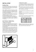
ceptacle should be 3” (from the bottom of the plastic
receptacle) above the refrigerator mounting floor. (see
FIG. 3). This allows easy access through the vent door.
The cord should be routed to avoid direct contact with
components that could damage the cord insulation.

12 Volts DC Connection

The refrigerator model NEA 1402 require a continuous
12 volt DC supply to maintain the automatic energy se-
lector system and the auto defrost control system to func-
tion.
The connection is made to the positive (+) and negative
(-) terminals of the terminal block on the back of the re-
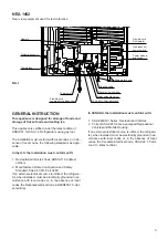
frigerator. (See FIG. 1). Correct polarity must be observed
when connecting to the DC supply.

Do not use the chassis or vehicle frame as one of the
conductors.
Connect two wires at the refrigerator and route to the
DC supply.
It is important that the wires to the 12-volt DC terminal is
of proper wire size.

Recommended conductor wires size and total conduc-
tor wires length are found in the table below.

Example: If the distance between the refrigerator and
the 12V DC supply is 20 ft., the total wire length is 40 ft.
and a wire size of 10 AWG should be used.

120 Volt AC
receptacle

3’’

FIG. 3

Length

Minimum Wire Size

<33 ft.

(<10m)

12 AWG

33 - 66 ft. (10 - 20m)

10 AWG

>66 ft.

(>20m)

8 AWG

Summary of Contents for NEA1402

Page 1: ...mable vapors and liquids in the vicinity of this or any other appliance WARNING Improper installation adjustment alteration service or maintenance can cause injury or property damage Refer to this man...

Page 2: ...ed must be electrically grounded in ac cordance with local codes or in the absence of local codes the National Electrical Code ANSI NFPA70 lat est edition In CANADA the installation must conform with...

Page 3: ...A delay function prevents rapid changes due to door openings etc Panel Indications Actual temperature of food in frozen food compartment Actual temperature of food in fresh food compartment AC operati...

Page 4: ...f the cord is 2 feet and therefore rec ommended that the receptacle be located to the right side of the refrigerator viewed from the rear The re ceptacle should be 3 from the bottom of the plastic rec...

Page 5: ...ce Caution Use care when installing the refrigerator This refrigerator is equipped with the latest vacuum insulated panel technology These insulating panels are located on the Top Back Bottom Sides an...

Page 6: ...The heat produced at the rear of the refrig erator will become trapped in this space making the top of the refrigerator hot and reduce the efficiency of the refrigerator Hole for drain water hose FIG...

Page 7: ...denser coil at the back of the refrigerator VENTILATION HEIGHTS CLEARANCES Minimum clearances in inches to combustible materials are G Top 0 K Side 0 L Bottom 0 M Rear 0 N See NOTE Clearance N below N...

Page 8: ...hicle should be leveled to prevent this loss of cooling The vehicle needs to be leveled only so it is comfortable to live in no noticeable sloping of floor or walls When the vehicle is moving the leve...

Page 9: ...l Hours are to the left and minutes to the right 2 Press SET key to adjust to local time PM or not should also be set here 3 Store each setting by pressing STORE key or use the automatic store functio...

Page 10: ...n has been blocked and is not circulating the air in the freezer compartment Check the fan by unscrewing the bottom part of the fan housing Try to rotate and look for ice build or other parts that can...

Page 11: ...tic personal has occurred Call a Dometic service center for assistance as soon as possible and notify displayed error code to the service agent Toll free number 800 544 4881 Error Message displayed He...

Page 12: ...ood Meat or fish whether raw or prepared can be stored in the frozen food storage compartment provided they are precooled first in the refrigerator They can be stored about three times longer in the f...

Page 13: ...ug holding the lid of the boiler casing and open the lid 6 Remove some insulation wool so that the heater is accessible 7 Turn and lift the heater out of its pocket 8 Fit the new heater into the pocke...

Page 14: ...em can be locked out to prevent unwanted use To Lock Out Press the Padlock pad for 3 5 seconds until the RED light above the Padlock comes on To Unlock Press the Padlock pad for 3 5 seconds until the...

Page 15: ...igure 13 4 Locate the adjusting screw under the protective cover Turn the screw counterclockwise to increase the size of cubes Turn the screw clockwise to decrease the cube size or if the mold is over...

Page 16: ...ws anchoring the refrigerator to the enclosure and slide the refrigerator out of the com partment When replacing the refrigerator make sure that the sealing strips are properly positioned Replacement...

Page 17: ...with an overheating protec tion An authorized service technician can check if it has been triggered or not NOTE AVOID SPRAYING WATER THROUGH THE REFRIGERATOR VENTS WHILE WASHING YOUR RV All the above...

Page 18: ...ck 12 in range between 8 5 18 V DC Lo or hl out of range 03 Air temperature Value in F in range hl or Lo out of range sensor fault sensors freezer fridge 04 Surface temperature Value in F in range hl...

Page 19: ...7 27 224 691 5 4 5 295 7 5 394 197 098 10 5 2 5 197 2x 5 2x MAX 1 00 MAX 25 MAX 1 00 MAX 25 295 7 5 45 197 2x 5 2x 394 197 098 10 5 2 5 16 811 427 12 756 324 28 051 712 5 32 106 815 5 59 842 1520 295...

Page 20: ...21 HOW TO FIT THE DOOR PANEL Freezer door Refrigerator door...

Page 21: ...e of the shelf will come loose Lower the right hand side of the wire shelf and let the left hand side slide out of the holes in the wall Slide the plastic plugs into the holes of the wall Snap the she...

Page 22: ...23 Fuse Type of component 3A A B D F G N 7 5A O P 3A T Optional ice maker heat kit 7 5A U 5A Z FUSES Refer to wiring diagram Fuses from left to right protect the following components...

Page 23: ...24 MO FO 0512...

Page 24: ...Patents pending U S 10 619 675 U S 10 620 177 U S 10 758 174 U S 10 758 175 U S 10 760 564 U S 10 760 565 This product is manufactured under license of U S Patent Number 6 019 447...

Reviews: