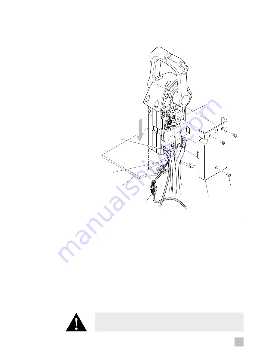
DASH
NEW CABLE TIE
GATEWAY
HARNESS
LPS HARNESS
CONNECTOR
LPS HARNESS
CONNECTOR
COVER
SCREW x 3
7-4
EN
Figure 7-4. Cable tie and cover installation.
8.
Install a new cable tie to secure the harnesses to the chassis and
re-install the cover. (Refer to figure 7-4.)
9.
Repeat steps 5–8 for the other side.
10.
Re-install the control head in the dash. Take care not to pinch or damage
any harnesses. Re-install the binnacle cover. This is a reversal of the
removal procedure shown in step 2 and 3.
11.
Twins and triples: From behind the dash, find the 9-pin connection from
the control head, disconnect it, and plug the connectors to the portion
of the gateway harness labeled ‘LED’ (Refer to figure 7-5).
Quads: Behind the trim switch panel you will find two 9-pin
connectors, one for each pair of engines (port pair and starboard pair).
Open the port connection and connect the gateway harness connectors
labeled ‘P LED.’ Repeat for the starboard connection with the connectors
labeled ‘S LED.’
CAUTION!
All harness runs should be sufficiently bundled and strain relieved to avoid
accidental damage.
Summary of Contents for OPTIMUS 360
Page 10: ...1 4 EN This page left intentionally blank ...
Page 12: ...2 2 EN This page left intentionally blank ...
Page 22: ...4 4 EN This page left intentionally blank ...
Page 38: ...6 14 EN This page left intentionally blank ...
Page 70: ...9 8 EN This page left intentionally blank ...
Page 78: ...10 8 EN This page left intentionally blank ...
Page 80: ...11 2 EN ...
Page 82: ...12 2 EN This page left intentionally blank ...
Page 84: ...A 2 EN This page left intentionally blank ...
Page 86: ...A 2 EN This page left intentionally blank ...
Page 88: ...A 4 EN This page left intentionally blank ...
Page 115: ......


