11-1
EN
11
OXE
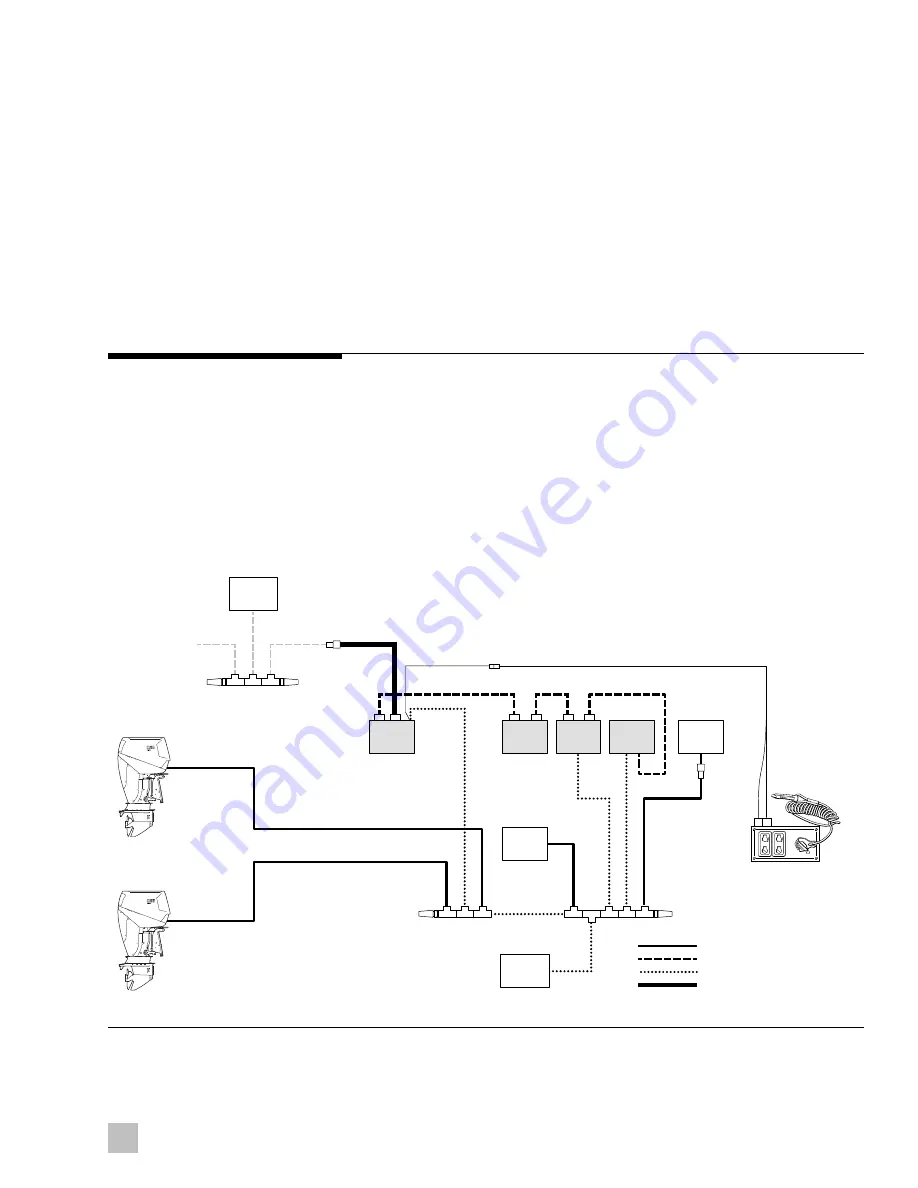
Figure 11-1.
To complete the system installation for an OXE EST engine you need to:
1.
Install the OXE control head (refer to installation instructions provided
by OXE)
2.
Complete the CAN network connections (11.1)
The OXE shift and throttle system and Optimus 360 system connect
together through the CAN2 network. CAN3 is used to broadcast system
information to a public NMEA2000 network.
1.
CAN2 connects to the OXE E-CAN network. This network should
already be adequately terminated with two terminating resistors. Do
not add more terminating resistors.
2.
CAN3 connects to the NMEA2000 instrumentation network.
3.
PCM ignition is connected to the key-on ignition switch panel.
Complete the CAN network as shown in figure 11-1.
11.1 OXE and Optimus 360 network
interconnection
Setup the system as instructed in Book 65. When prompted to select a
Shift and Throttle type, select i7700.
RUN
OFF
OXE E-CAN
CAN1 FTCAN PRIVATE NETWORK
CAN2 PRIVATE NETWORK
CAN3 PUBLIC N2K NETWORK
PORT
ENGINE
STBD
ENGINE
CM1
00
X
X
CM20
30
4
CM1
00
X
X
52
" H
AR
N
ESS
COLOR
CANtrak 1
JOYSTICK 1
HELM 1
PCM
CM20406
72" HARNESS
CM204XX
CM100XX
IGNITION
CM20503
CM100XX
12V
PURPLE x 2
CONTROL
HEAD 1
TERMINATOR
CM10051
TERMINATOR
CM10052
OXE
ENGINE
DISPLAY
PUBLIC N2K
DEVICES
SEASTATION
/SEAWAY
SENSOR
IGNITION
SWITCH PANEL
P S
Summary of Contents for OPTIMUS 360
Page 10: ...1 4 EN This page left intentionally blank ...
Page 12: ...2 2 EN This page left intentionally blank ...
Page 22: ...4 4 EN This page left intentionally blank ...
Page 38: ...6 14 EN This page left intentionally blank ...
Page 70: ...9 8 EN This page left intentionally blank ...
Page 78: ...10 8 EN This page left intentionally blank ...
Page 80: ...11 2 EN ...
Page 82: ...12 2 EN This page left intentionally blank ...
Page 84: ...A 2 EN This page left intentionally blank ...
Page 86: ...A 2 EN This page left intentionally blank ...
Page 88: ...A 4 EN This page left intentionally blank ...
Page 115: ......


