background image

11.

Maintenance:

‘ C A U T I O N ’

‘Risk of electric shock More  than one power supply.
Diinect all power supplies before servicing’.

LP. 

gas equipment:

The burner  (fig. 3) is fitted with a jet No..21 which is suitable for use with Propane gas at a
supply pressure of 11 inches, water gauge. The orifice in the jet is very small and must never
be cleaned by means of a pin or a similar instrument, as this could damage the orifice. Should

the jet require deaning for some reason, it should be washed in alcohol and blown through
with air.

11.1 Cleaning gas burner and jet:

Once or twice a year, or depending on use, check whether the f&me is blue-coloured. For this
inspect the flame through burner flame opening (fig. 2.9) a yellow flame is sign of a bad
combustion. The procedure for cleaning the flue and the burner assembly, is as follows:

a:
b:

unscrew rear cover of refrigerator box.
disconnect and remove gas pipe from the burner. For this operation you need a 13/32" (10
mm) spanner for the union nut (fig. 3.1).

c:

d:

e:

f:

g:

unscrew the counter nut (fig. 3.2) of the jet (fig. 3.3) with a 1/2" (12 mm) spanner and
remove guard (fig. 3.4).

unscrew security-and guard plate (fig. 3.5,3.7) of the burner pipe (fig. 3.6) which are
fastened by a screw, push the burner pipe from the jet and remove the jet from the boring.

wash the jet with alcohol and blow through with air to check that the opening is quite
dean. Do not use a probe.
clean the burner pipe ensuring its combustion- and aeration openings are free from dust.
refit all parts, ensuring the burner is property retained. Gas connections should be tight,

but not overnight After replacing, check all gas joints for tightness as descrii in the next
item.

All instructions under item 11.1 must only be made by an expert, preferably by a

licenced gas fitter.

11.2 

Checking for gas leaks:

Periodically, and after each service the entire gas installation should be checked for leaks. Test
all pipe connections with soapy water (not with a flame), watching for bubbles - see item 2
Liquid Gas Operation.

11.3 Heaters:
Heat is supplied 

to the 

boiler of the cooling unit by two separate 75 

W heaters, one

 for 12 V

d.c. and one for 120 

V a.c.. If a new heater has to be fitted, the procedure is 

as follows:

7

Summary of Contents for RC 2000

Page 1: ...for INSTALLATION and USE of portable REFRIGERATOR MODEL RC2000 BEFORE USING YOUR PORTABLE REFRIGERATOR PLEASE READ THESE INSTRUCTIONS CAREFULLY AND RETAIN THEM FOR FUTURE REFERENCE Dometic 820 950180...

Page 2: ...fessional help FOR YOUR SAFETY Do not store or use gasoline or other flammable vapours and liquids in the vicinity of this or any other appliance WARNING This refrigerator consumes air oxygen Provide...

Page 3: ...as applicable ANS 221 74 b 1989 Portable Refrigerator in Canada CAN1 11 4 M79 The overall dimensions of the refrigerator are given in fig 1 For installation for maintaining proper clearances between c...

Page 4: ...Communication 2 Liquid Gas Operation The refrigerator may only be operated using a self contained 14 or 16 4 oz propane HD 5 gas bottle which is to be connected to the refrigerator by means of the su...

Page 5: ...two or more power sources i e gas and 120 V or 12 V SIMULTANEOUSLY The cooling unit will not operate properly in this case and damage may be caused 4 1 a b c d e f g 4 Propane gas operation Lighting...

Page 6: ...ng transferred from one food to another foods should always be stored in covered dishes plastic bags or wrapped in foil or greaseproof paper NEVER PUT HOT FOOD INTO THE REFRIGERATORI Avoid using large...

Page 7: ...of the cabinet should be wiped with a dean damp cloth and polished with a dean soft duster NEVER USE STRONG CHEMICALS OR ABRASIVE CLEANING MATERIALS ON ANY PART OF THE REFRIGERATOR 10 What to do when...

Page 8: ...g unscrew the counter nut fig 3 2 of the jet fig 3 3 with a 1 2 12 mm spanner and remove guard fig 3 4 unscrew security and guard plate fig 3 5 3 7 of the burner pipe fig 3 6 which are fastened by a s...

Page 9: ...that the correct clearances for air circulation at the back and above the top of casing have been allowed for see item 1 b Thermostat incorrectly used see item 5 c Evaporator ice tray support heavily...

Page 10: ...der holder Gas valve Pressure regulator with hose Gas cylinder Gas connection inlet Gas thermostat knob Safety device Piezo igniter Burner flame opening Electric thermostat knob 120 V flame indicator...

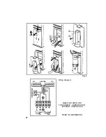
Page 11: ...AC HEATER DC Fig 4 Wiring Diagram MANUFACTURED FOR THE DOMETIC CORPORATION ELKHART INDIANA USA MADE IN LUXEMBOURG 10...

Reviews: