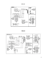
TESTING LP GAS SAFETY SHUTOFF
The gas safety shutoff must be tested after the re-
frigerator is connected to the LP gas supply.
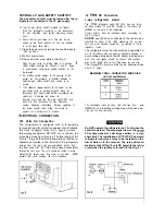
To test the gas safety shutoff, proceed as follows:
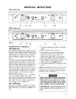
1 . Start the refrigerator according to the instructions
for Gas Operation. See section Operating Instruc-
tions.
2. Check that the gas flame is lit. This can be ob-
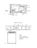
served on the flame indicator E. The red indicator
is in the green field, (ON).
3. Close the gas valve by turning the knob A back to
“OFF” position.
4. Wait for one minute.
5. Remove burner cover plates. (See fig. 1).
Open the gas valve by turning knob A to position
(GAS) without pushing the buttons C and D. Apply
a non-corrosive commercial bubble solution to the
burnerjet.
6. No bubbles should appear at the opening of the
burner jet. The presence of bubbles indicates a
defective gas safety shutoff, and service is re-
quired.
7. If no bubbles
present at the burner jet, the
gas safety valve is working properly. Rinse jet
thoroughly with fresh water before proceeding. Be
careful not to damage the burner jet.
Replace cover and turn the main switch OFF and
back ON. See instruction for Gas Operation.
section Operating Instructions. Normal operation of
the burner should return. Allow the burner to
operate for a minimum of 5 minutes.
CONNECTION
120 Volts AC Connection
The refrigerator is equipped with a three-prong
(grounded) plug for protection against shock hazards
and should be plugged directly into a properly grounded
three-prong receptacle. DO NOT cut or remove the
grounding prong from this plug. The free length of the
cord is 1.6 and therefore recommended that the re-
ceptacle be located to the left side of the refrigerator
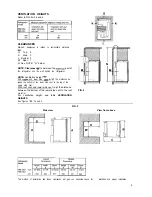
(viewed from the rear) and approximately46 inches from
the floor (see FIG. 8). This allows easy accessibility
through the vent door. The cord should be routed to avoid
contacting the burner cover. flue cover, or any other
ponents that could damage the cord insulation.
9
12
DC Connection
J-way refrigerator model
The
refrigerator model RM 2353, has one termi-
nal block marked “12 volts DC” located at the bottom left
on the back of the refrigerator.
Correct polarity must be observed when connecting to
the DC supply.
DO NOT
use the body or chassis of the vehicle as a
substitute for either of the
conductors. Do not con-
nect any other electrical equipment
lighting to the re-
frigerator circuit.
The refrigerator must be connected by a separate cir-
cuit to the battery with two wires of adequate capacity to
avoid voltage drop when the DC heater is being oper-
ated. The wire gauge should be chosen with consider-
ation to the length: refer to the Table below for wire size.
The
DC circuit must be fused. Maximum fuse
size is 15 amps.
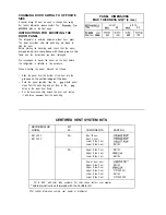
MAXIMUM TOTAL CONDUCTOR WIRE SIZE
(In Feet and Meters)
The connections must be clean, tight and free from
If not, a resulting voltage drop will cause a de-
c r e a s e d c o o l i n g c a p a c i t y
Do NOT operate the refrigerator on 12 volt when the
vehicle is parked. The amperage draw of the
DC heating element can discharge a battery in
short time. The installation of
DC operated
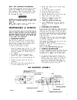
refrigerator requires a relay to be installed on the
tow vehicle or in the caravan. The relay will auto-
matically shut off the 12 volt DC power to the refrig-
erator when the ignition is turned off. (See fig. 9).
7

