background image

1.3 RM2201 OPERATION

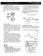
115 Volt
SUPPLY

Thermostat

\

3

A.

1)

2)

3)
4)
5)

6)

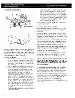
GAS OPERATION

Rotate selector to “OFF” position.

Turn gas handle to the left.
Turn gas thermostat knob to #4 setting.

Press gas safety valve plunger up and hold.
Push piezo igniter plunger repeatedly until

flame is observed at “6”.

When flame is lit:
a. Discontinue pushing the piezo plunger.

b. BUT continue to hold up on the safety

valve plunger for about 15 seconds.

c. If flame goes out when plunger is re-

leased, repeat Steps 4 through 6.

Turn the handle (8) of the gas valve (7) away
from the back of the cabinet to shut off gas

operation.

NOTE: The ice tray shelf should now show signs
of cooling after an hour. If the gas has to be re-lit
when the ice making compartment is still cold,
turn the thermostat dial (3) to MAX. Repeat
Steps 4 through 6 and, return the thermostat to

its normal setting only after the burner is lit.

The refrigerator has a flame failure device which
will automatically shut off the gas to the burner if
the flame is blown out. While the plunger (4) is

being held in, this device is temporarily inopera-
tive.

DANGER - DO NOT hold this plunger in
unless attempting to light the gas burner.

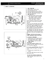
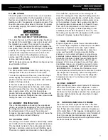
B. ELECTRIC OPERATION

1) Turn gas valve to “OFF” position (with the

handle pointing away from the cabinet).

2) Turn voltage selector switch so desired

voltage marking is next to the selector

position indicator.

For Example:

If 115 volt AC operation is desired, rotate
selector to “110-1 15V” position and connect the
115 volt electrical supply cord.

- or -

If 12 volt DC ooeration is desired, rotate selector
to “12V”  position and supply 12 volt battery
power.

3) Turn the electric thermostat knob to #4

position.

The ice tray shelf should show signs of cooling

after about an hour.

TO SHUT OFF ELECTRIC OPERATION:

Rotate the voltage selector switch (2) to the
“OFF” position.

5

Summary of Contents for RM2150 Series

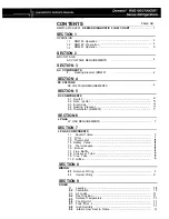
Page 1: ...ction for making accurate analyses of certain conditions Provided is a diagnostic chart leading a qualified mechanic into the service manual pages to locate and solve symptoms which may occur Dometic...

Page 2: ...trode 5 4 Heating Element t 5 5 Thermostat RM2201 7 SECTION 6 LP GAS LP GAS REQUIREMENTS 7 SECTION 7 LP GAS COMPONENTS 7 1 Shut Off Valve 7 7 2 Filter 7 7 3 Thermostat 7 4 Safety Valve t 7 5 Thermocou...

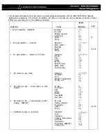
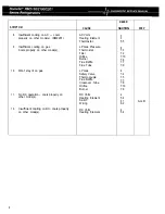
Page 3: ...3 No gas operation sparks but no flame Operation 1 1 1 2 1 3 LP gas 6 Filter 7 2 Orifice 7 10 Burner 7 6 Shut off Valve 7 1 Safety Valve 7 4 Thermocouple 7 5 4 No cooling on any mode Operation 1 1 1 2...

Page 4: ...ode s Thermostat 7 3 Filter 7 2 Orifice 7 10 Burner 7 6 Flue Baffle 7 7 Flue Tube 7 9 10 Won t stay lit on gas LP Gas 6 Safety Valve 7 4 Thermocouple 7 5 Flue Baffle 7 7 Crossover Tube 7 8 Orifice 7 1...

Page 5: ...hich will automatically shut off the gas to the burner if the flame is blown out While plunger 10 is being held in this device is temporarily inopera tive DANGER DO NOT hold this plunger in unless att...

Page 6: ...r if the flame is blown out While the plunger C is being held in this device is temporarily inoperative TO SHUT DOWN Turn the handle of the gas valve A away from the cabinet B 12 VOLT ELECTRIC OPERATI...

Page 7: ...turn the thermostat to its normal setting only after the burner is lit The refrigerator has a flame failure device which will automatically shut off the gas to the burner if the flame is blown out Whi...

Page 8: ...manner Remove wires from the assembly In the ON position continuity should exist In the OFF position no continuity should exist If either check is incorrect the switch is defective and must be replace...

Page 9: ...he refrig erator should be 11 inches water column with half of all BTU s of the RV turned on With all other appliances turned off the pressure to the refrigerator should not exceed 12 inches water col...

Page 10: ...o the burner if the flame goes out for any reason This is to ensure that a concentration of unburned gas does not accumulate in the refrigerator vent area To check the safety valve use a known good th...

Page 11: ...create a potentially dangerous condition The correct orifice for the RM2150 RM2190 and RM2201 is Size F NOTE Always use the proper orifice Never use a larger orifice as this could cause a lack of cool...

Page 12: ...air produced by the action of the cooling unit out away from the installation of the refrigerator The refrigerator extracts heat from the interior of the refrigerator cabinet and dissipates the heat...

Page 13: ...ling process include hydrogen ammonia water and a rust inhibiting agent There are no repairs recommended on the cooling unit If it is defective replace with a new cooling unit To check the cooling uni...

Reviews: