background image

2

EN

Contents 

Manual Refrigerator

1  Explanation of Symbols and Safety 

Instructions   . . . . . . . . . . . . . . . . . . . . . . . . . . . . 2

1.1 

Recognize Safety Information  . . . . . . . . . . . . . 2

1.2  Understand Signal Words . . . . . . . . . . . . . . . . 2
1.3  Supplemental Directives . . . . . . . . . . . . . . . . . 3
1.4  General Safety Messages  . . . . . . . . . . . . . . . . 3

2  Intended Use  . . . . . . . . . . . . . . . . . . . . . . . . . . . 4

3 Troubleshooting   . . . . . . . . . . . . . . . . . . . . . . . . 4

4  General Information  . . . . . . . . . . . . . . . . . . . . . 6

4.1  Tools and Materials  . . . . . . . . . . . . . . . . . . . . . 6
4.2  Component Locations. . . . . . . . . . . . . . . . . . . 7
4.3 Terminology . . . . . . . . . . . . . . . . . . . . . . . . . . . 7

5  Wiring Diagrams  . . . . . . . . . . . . . . . . . . . . . . . . 8

6  Diagnostic Procedures  . . . . . . . . . . . . . . . . . . . 8

7  Installation Issues  . . . . . . . . . . . . . . . . . . . . . . 13

7.1 

Power Issues   . . . . . . . . . . . . . . . . . . . . . . . . . 13

7.2  Gas Pressure Issues  . . . . . . . . . . . . . . . . . . . . 13
7.3  Installation Issues  . . . . . . . . . . . . . . . . . . . . . . 13
7.4  Ambient Temperature Issues . . . . . . . . . . . . . 14
7.5  Humidity Issues  . . . . . . . . . . . . . . . . . . . . . . . 14
7.6  Altitude Issues  . . . . . . . . . . . . . . . . . . . . . . . . 14
7.7  RF Interference Issues   . . . . . . . . . . . . . . . . . . 14

8  Service Procedures  . . . . . . . . . . . . . . . . . . . . . 14

8.1  Removing the Refrigerator from an  

Enclosure  . . . . . . . . . . . . . . . . . . . . . . . . . . . . 15

8.2  Performing a Gas Leak Test  . . . . . . . . . . . . . . 15
8.3  Replacing the Burner Assembly   . . . . . . . . . . 15
8.4  Cleaning the Jet  . . . . . . . . . . . . . . . . . . . . . . . 16
8.5  Replacing the Cooling Unit . . . . . . . . . . . . . . 16
8.6  Replacing the Door  . . . . . . . . . . . . . . . . . . . . 17

8.7  Testing the Door Gasket  . . . . . . . . . . . . . . . . 17
8.8  Repairing the Door Gasket  . . . . . . . . . . . . . . 18
8.9  Adjusting the Position of the Electrode   . . . . 18
8.10   Replacing the Electrode . . . . . . . . . . . . . . . . 18
8.11  Replacing the Flue Baffle . . . . . . . . . . . . . . . . 18
8.12  Replacing the Gas Valve  . . . . . . . . . . . . . . . . 19
8.13  Testing a Heating Element for Resistance . . . 19
8.14  Replacing a Heating Element  . . . . . . . . . . . .20
8.15  Replacing the Piezo . . . . . . . . . . . . . . . . . . . .20
8.16  Replacing a Switch   . . . . . . . . . . . . . . . . . . . . 21
8.17  Replacing the Thermocouple  . . . . . . . . . . . . 21
8.18  Replacing the Thermostat  . . . . . . . . . . . . . . . 21
8.19  Replacing the Ventilation Fan  . . . . . . . . . . . .22
8.20  Replacing the Ventilation Fan Switch  . . . . . .22

9 Disposal  . . . . . . . . . . . . . . . . . . . . . . . . . . . . . . 23

10  Replacement Parts   . . . . . . . . . . . . . . . . . . . . . 23

Contents

Service Center & Dealer Locations

Visit: www.dometic.com

Read these instructions carefully.

1  Explanation of Symbols and 
Safety Instructions

This manual has safety information and instructions to 
help you eliminate or reduce the risk of accidents and 
injuries. 

1.1  Recognize Safety Information


This is the safety alert symbol. 

It is used to alert 

you to potential physical injury hazards. Obey all 
safety messages that follow this symbol to avoid 
possible injury or death.

1.2  Understand Signal Words

A signal word will identify safety messages and property 
damage messages, and also will indicate the degree or 
level of hazard seriousness.


DANGER!

Indicates a hazardous situation that, if 

not

 avoided, 

will result in death or serious injury.

PN

Summary of Contents for RM2193

Page 1: ...ble vapors and liquids in the vicinity of this or any other appliance WHAT TO DO IF YOU SMELL GAS Do not try to light any appliance Do not touch any electrical switch Do not use any phone in your recr...

Page 2: ...the Electrode 18 8 11 Replacing the Flue Baffle 18 8 12 Replacing the Gas Valve 19 8 13 Testing a Heating Element for Resistance 19 8 14 Replacing a Heating Element 20 8 15 Replacing the Piezo 20 8 16...

Page 3: ...ns for the proper installation of this appliance Failure to obey this danger notification can result in improper installation causing carbon monoxide poisoning that will result in death or serious inj...

Page 4: ...n death or serious injury CAUTION BURN FROSTBITE OR FROSTNIP HAZARD Failure to obey the following cautions could result in minor or moderate injury Do not touch cold surfaces or stored items in freeze...

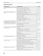
Page 5: ...ture level set by the knob on the gas valve is too low for the ambient temperature 10 The refrigerator does not get cold enough in any operating mode Improper installation caused an imbalance in the a...

Page 6: ...g Element 10 Piezo 11 Switch AC 11 Switch DC Thermocouple 11 Thermostat 11 Ventilation Fan Switch 12 4 General Information This section provides reference information on the tools components and termi...

Page 7: ...be welded to the burner that conducts heat during gas operation to provide proper heat exchange to the cooling unit Cooling Unit A sealed ammonia based absorption cooling system Electrode Passes the s...

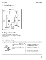
Page 8: ...allation Issues on page 13 for more detail Component Diagnostic Question Action Based On Status Page Burner Assembly Does the refrigerator not operate in gas mode Does the refrigerator not get cold en...

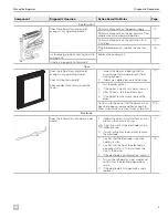
Page 9: ...osing properly 2 If damage is observed replace the door 17 1 Test the door gasket 2 If the gasket is weak at any point repair it 3 After 24 hours test the gasket again 4 If the gasket remains weak rep...

Page 10: ...Does the fresh food compartment freeze Adjust the knob on the gas valve to the appropriate setting for the operating conditions I IIf the ambient temperature is above 80 F 27 C or the door of the ref...

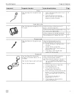
Page 11: ...dry 7 1 Confirm that the gas is lighting but not staying lit 2 Confirm that the voltage of the thermocouple while in the burner flame is between 14 30 mV 3 If the voltage is out of specification repla...

Page 12: ...that will activate the ventilator fan I IInstallation location varies by model and installer The temperature range for activation varies by model 2 If the temperature is within specification does the...

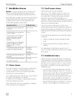
Page 13: ...ues Check that the gas pressure is between 10 5 11 5 in W C ideally as close to 11 in W C at the refrigerator as possible Perform the check with a minimum of 50 ideally 100 of other gas fired applianc...

Page 14: ...rformance if the unit is not installed and ventilated according to specification Refer to Installation Issues on page 13 for more details I IIf the ambient temperature is below 32 F 0 C operating the...

Page 15: ...closure 7 Confirm there are no LP gas leaks Refer to Performing a Gas Leak Test on page 15 for more details 8 2 Performing a Gas Leak Test WARNING FIRE AND OR EXPLOSION HAZARD Do not use matches candl...

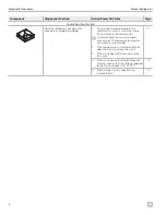
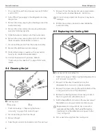
Page 16: ...Disconnect the gas line from the jet 3 Remove the jet 4 Soak the jet in an alcohol based solvent for one hour 5 Remove it from the cleaner and use compressed air to blow out any residual deposits Let...

Page 17: ...cing the Door q w 7 Removing the Door qDoor Hinge w Door 1 Locate and gain access to the door hinges Refer to Removing the Refrigerator from an Enclosure on page 15 if removing the refrigerator is nec...

Page 18: ...the clip holding the electrode in position on the burner assembly I ITo avoid cracking the ceramic insulator do not try to adjust the electrode without first loosening the screw 4 Adjust the electrod...

Page 19: ...valve and cap the gas line 4 Disconnect the thermocouple from the bottom of the gas valve 5 Remove the knob from the top of the gas valve selector switch 6 Remove the nut securing the gas valve to th...

Page 20: ...e thermostat ground and power switch 7 Remove the defective heating element from the pocket within the burner tube 8 Perform these steps in reverse with the new heating element to complete the replace...

Page 21: ...the steps in Replacing the Burner Assembly on page 15 to release the thermocouple from the clip 2 Remove the screws securing the switch panel to the back of the refrigerator 3 Slide the switch panel o...

Page 22: ...e ventilation fan on the rear of the refrigerator 4 Disconnect the wiring to the fan 5 Remove the screws securing the fan to the mounting bracket 6 Remove the defective fan from the rear of the refrig...

Page 23: ...iate recycling waste bins whenever possible Consult a local recycling center or specialist dealer for details about how to dispose of the product in accordance with all applicable national and local r...

Page 24: ...Mobile living made easy dometic com YOUR LOCAL DEALER dometic com dealer YOUR LOCAL SUPPORT dometic com contact YOUR LOCAL SALES OFFICE dometic com sales offices...

Reviews: