2
INSTALLATION INSTRUCTIONS ____________ 3
GENERAL INFORMATION . . . . . . . . . . . . . . . . . . . . . . . . . 3
PACKAGING . . . . . . . . . . . . . . . . . . . . . . . . . . . . . . . . . . . . 3
VENTILATION REQUIREMENTS . . . . . . . . . . . . . . . . . . . . 3
CLEARANCES . . . . . . . . . . . . . . . . . . . . . . . . . . . . . . . . . . 3
DIMENSIONS . . . . . . . . . . . . . . . . . . . . . . . . . . . . . . . . . . . 4
INSTALLING THE REFRIGERATOR . . . . . . . . . . . . . . . . . 4
SECURING THE REFRIGERATOR . . . . . . . . . . . . . . . . . . 4
CONNECTIONS . . . . . . . . . . . . . . . . . . . . . . . . . . . . . . . . . 4
RE-HINGING THE DOOR . . . . . . . . . . . . . . . . . . . . . . . . . 6
MOUNTING THE DOOR PANEL . . . . . . . . . . . . . . . . . . . . . 6
REFRIGERATOR REMOVAL . . . . . . . . . . . . . . . . . . . . . . . 6
OPERATING INSTRUCTIONS ______________ 7
GAS, AC AND DC OPERATION . . . . . . . . . . . . . . . . . . . . . 7
REGULATING THE TEMPERATURE . . . . . . . . . . . . . . . . . 8
TURNING OFF THE REFRIGERATOR . . . . . . . . . . . . . . . . 8
STORAGE COMPARTMENTS . . . . . . . . . . . . . . . . . . . . . . 8
PRODUCT CARE . . . . . . . . . . . . . . . . . . . . . . . . . . . . . . . . 9
MAINTENANCE & SERVICE _______________ 9
REPLACING THE HEATER . . . . . . . . . . . . . . . . . . . . . . . . 9
PERIODIC MAINTENANCE . . . . . . . . . . . . . . . . . . . . . . . . 9
TROUBLESHOOTING . . . . . . . . . . . . . . . . . . . . . . . . . . . 10
APPENDIX ____________________________ 11
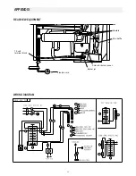
REARVIEW EQUIPMENT . . . . . . . . . . . . . . . . . . . . . . . . . 11
WIRING DIAGRAM . . . . . . . . . . . . . . . . . . . . . . . . . . . . . . 11
CONTENTS
INTRODUCTION
We are pleased that you have chosen this refrigerator and
hope you will derive much satisfaction from using it.
The refrigerator is designed for storage of foods and storage
of frozen foods and making ice.
The installation and servicing should only be carried out by
an authorized/qualified person.
It is important to read through these instructions carefully
before using the refrigerator. To ensure good refrigeration and
economical operation, the refrigerator must be installed and
used as described in these instructions.
Follow the instructions in this manual. The refrigerator is
quality guaranteed. However, we are not responsible for any
failures caused by improper adjustments and unfavourable in-
stallation conditions. Please contact service point or distribu-
tor service dept. for assistance.
DATA PLATE
Check the data plate, located inside the refrigerator, to ensure
that you have received the right model and that it is suitable
for the available gas supply and pressure.
The right gas pressure is . . . . . . . . . . . . . . . . . . 2.75 kPa
The right voltage is . . . . . . . . . . . . . . . . . . 230 - 240 volt
The right gas consumption is . . . . . . . . . . . . . . 1.05 MJ/h
The data plate contains e. g. the following details:
Model designation . . . . . . . . . . . . . . . . . . . . . . . . . . . . . .
Product number . . . . . . . . . . . . . . . . . . . . . . . . . . . . . . . .
Serial number . . . . . . . . . . . . . . . . . . . . . . . . . . . . . . . .
Since these details will be needed if you have to contact serv-
ice personnel, it is a good idea to make a note of them here.
SYMBOLS
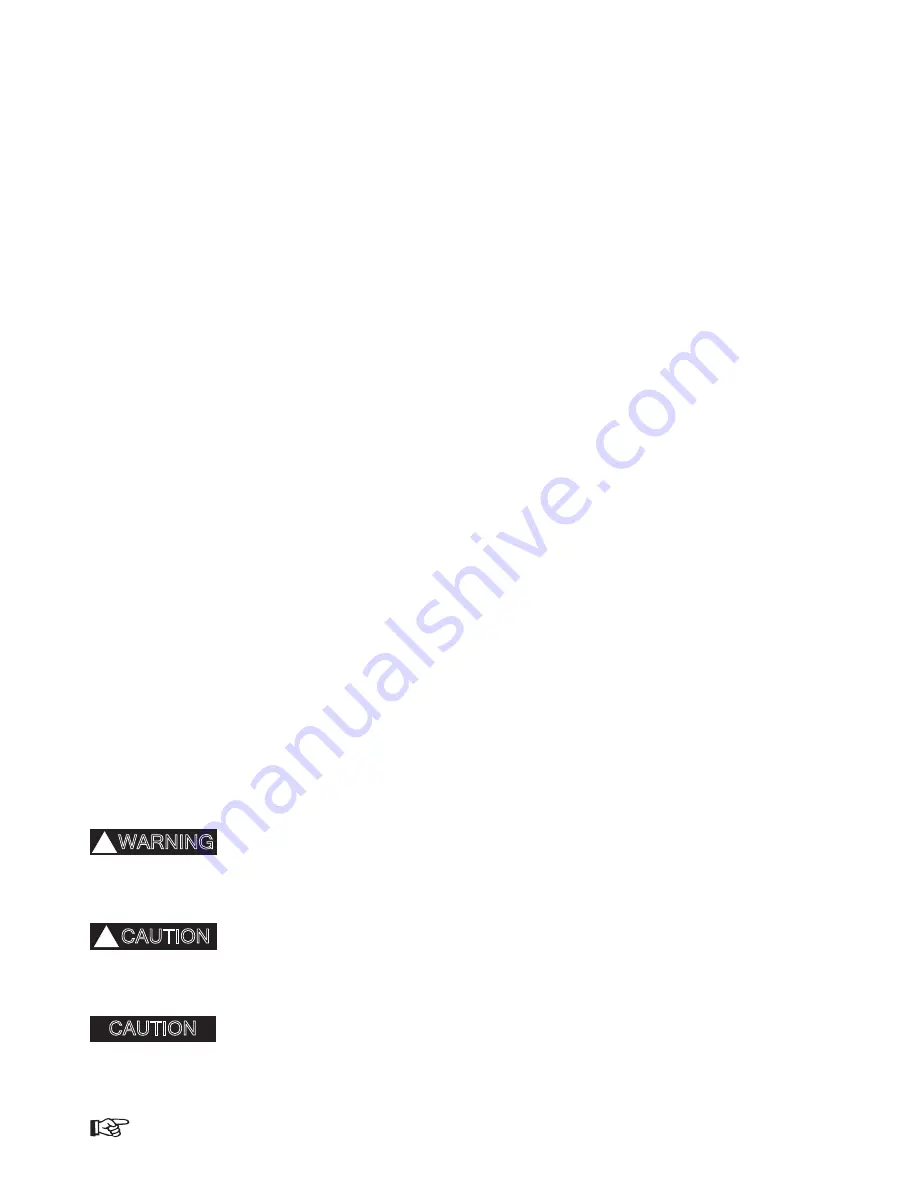
The following symbols are used throughout the manual:
Indicates a potentially hazardous
situation, which, if not avoided,
could result in death or serious
injury.
Indicates a potentially hazardous
situation, which, if not avoided,
may result in minor or moderate
injury.
Used without the safety alert
symbol indicates, a potentially
hazardous situation which, if not
avoided may result in property
damage.
Step-by-step
instructions
CAUTION
!
WARNING
!
CAUTION
Summary of Contents for RM2350
Page 12: ...54 219 MAW41A01...

