background image

15

CERTIFIED VENT SYSTEM KITS

REFRIGERATOR

KIT

MODEL

NO.

COMPONENTS

PART NO.

RM 2454

3A

Roof Base

3103633.XXX*

Roof Cover

3103634.XXX*

Lower Side Vent

3109350.XXX*

*

Fill in “XXX” with color code numbers. For color codes, contact your supplier.

For further information contact your dealer or distributor.

1

1

1

1

1

1

2

3

3

4

5

Summary of Contents for RM2454

Page 1: ...er appliance WARNING Improper installation adjustment alteration service or maintenance can cause injury or property damage Refer to this manual For assistance or additional information consult a qual...

Page 2: ......

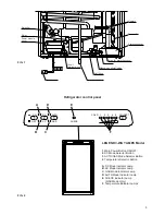
Page 3: ...or Button A DC Mode Indicator Lamp B AC Mode Indicator Lamp C GAS Mode Indicator Lamp D AUTO Mode Indicator Lamp E CHECK Indicator Lamp GAS Mode Only F Temperature Indicator Lamps 1 2 3 4 B A D E C F...

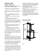
Page 4: ...ace of the mobile home or recreational vehicle Openings for air supply or for venting of combustion products shall have a minimum dimension of not less than 1 4 inch Proper installation requires one l...

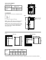
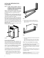
Page 5: ...tilation height see table VENTILATION HEIGHTS See Figures 3 and 4 This method of installation and these clearances will give you adequate space for service and proper installation G Overall Recess Ref...

Page 6: ...frigerator After the refrigerator is put in place ensuring a com bustion seal at the front frame the refrigerator is to be secured in the enclosure with six screws not included The screws have to be i...

Page 7: ...ion to the gas supply are required contact your dealer or distributor TESTING LP GAS SAFETY SHUTOFF The gas safety shutoff must be tested after the re frigerator is connected to the LP gas supply To t...

Page 8: ...f running time before the cooling unit is fully operational The tubing in the evaporator section is specifically sloped to provide a continuous movement of liquid ammonia flowing downward by gravity t...

Page 9: ...he GAS mode indicator lamp C will illuminate and the control system will automatically switch to GAS operation 3 If the CHECK indicator lamp E illuminates and the GAS mode indicator lamp C is off the...

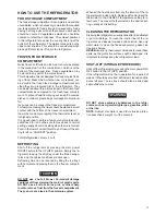
Page 10: ...ntil the main power ON OFF button is pressed to the OFF then ON position DC MODE When operating in the DC mode the DC mode indicator lamp A will be illuminated All other mode lamps will be off The DC...

Page 11: ...dest part of the compartment which is at the bottom of the aluminum liner Frozen vegetables may be stored in any part of the compartment This compartment is not designed for deep or quick freez ing of...

Page 12: ...efrigerator to the enclosure and slide the refrigera tor out of the compartment When replacing the refrigerator make sure that the seal ing strips are properly positioned Replacement is the reverse of...

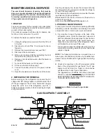
Page 13: ...all burner being careful that the end of the burner fits into the slot on the burner bracket Check to make sure slots are centered under the flue tube and the thermocouple is positioned properly tip o...

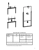
Page 14: ...ctions are read thoroughly When mounting the panel proceed as follows See figure page 15 A Open the door 90 degrees On new refrigerators the decoration strip is taped inside the door if installed on t...

Page 15: ...OMPONENTS PART NO RM 2454 3A Roof Base 3103633 XXX Roof Cover 3103634 XXX Lower Side Vent 3109350 XXX Fill in XXX with color code numbers For color codes contact your supplier For further information...

Page 16: ...16 MO FO 0413 RM 2454...

Reviews: