17.
THERMOELECTRIC
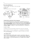
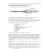
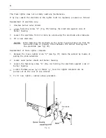
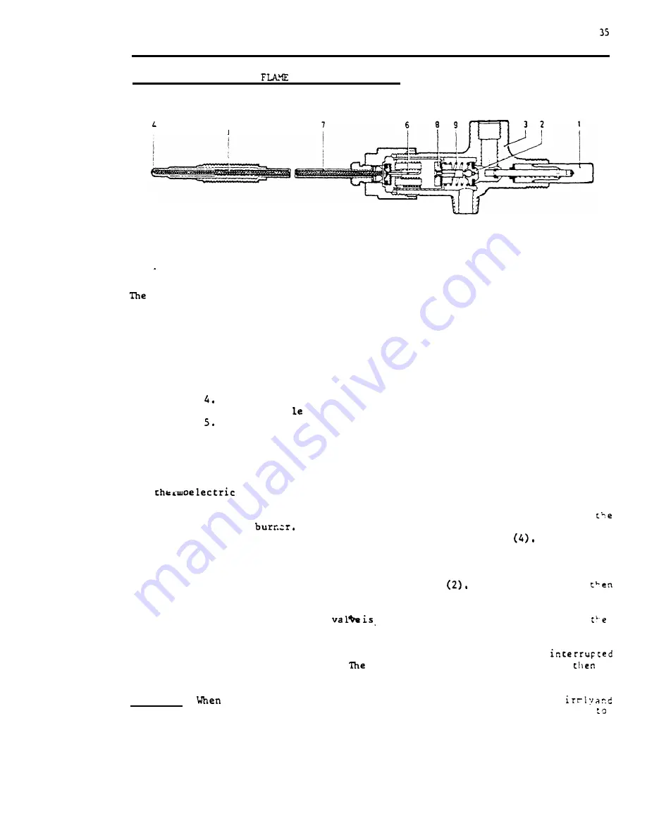
FAILURE SAFETY DEVICE (see fig, 58)
All
A l l
models equipped with an automatic failure device.
S
Fig. 58
gas operated or combined gas/electric refrigerator models dealt with in this
service instruction are equipped with an automatic failure device.
purpose of incorporating an automatic flame failure device in the burner assem-
bly is to prevent unburned gas to escape from the burner and to avoid a fire hazard,
if, for some reason or other, the flame has been extinguished or blown out,
The safety device consists of the following parts:
1.
2.
3.
6.
7.
8.
9.
Spring loaded push button
Gas valve
Housing
Sensing clement with the hot junction of the
thermocoup (Feeler)
Enamel insulated copper thread
Electromagnet
Outer tube
Armature
Spring
The
safety device functions as follows:
By pressing the push button (1) the gas valve (2) is opened and the gas can pass
housing (3) on to the
At the burner the feeler (4) is located. When the gas
flame of the burner is lit, some heat is transferred to the feeler
The hot
junction of the thermocouple is thus heated and an electric current is g e n e r a t e d .
This current passes through the copper wire (5) to the electromagnet (6) and back
through the outer tube (7). As soon as the electric current is generated, the
electromagnet attracts the armature (8) with the valve
The push button can
be released,
As long as current is flowing, the
kept open and allows gas to pass co
burner.
When the flame is extinguished, the heat transfer to the hot junction is
and no electric current is generated.
armature (8) with the valve (2) is
forced back by the spring (9) and the gas flow through the valve (2) is c l o s e d .
Important:
lighting the burner the push button (1) should be pressed f
held in that position about 10 seconds, otherwise the gas may not get
the burner properly,

