4
DIAGNOSTIC SERVICE MANUAL
Dometic
®
RM2604/2804
Refrigerators
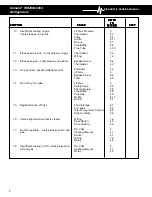
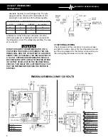
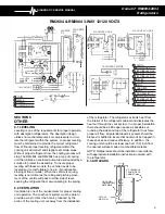
sure switch is wired properly per the wiring diagram (See
Sec. 7.2).
When the switch is in the off position a continuity reading
SHOULD NOT be indicated on any terminals. If the
above test results are correct, DO NOT REPLACE the
switch. If any one of the above tests are not correct
REPLACE the switch.
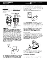
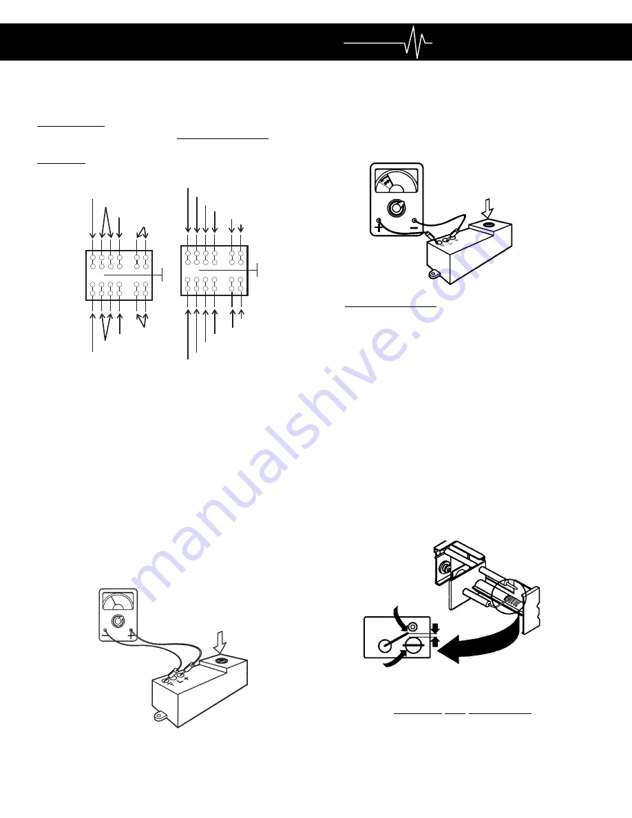
4.2 IGNITER
The igniter is an electronic device that produces high
voltage to create a spark at the burner, only on gas
mode. It also produces an increased DC voltage at the L
terminal which is directed to the indication lamp each
time a spark is produced. First, check that the switch is
in the gas mode and is completing the circuit (See Sec.
4.1). Next, verify proper voltage at the positive (+) and
ground (-) terminals of the igniter. The reading should be
within one volt of incoming voltage at the igniter and
lamp terminal block. A voltage drop of more than one
volt would indicate a loose connection (See Sec. 7.2).
No voltage would indicate an open circuit, check switch
(See Sec. 4.1), wiring (See Sec. 7.2) and DC voltage
requirements (See Sec. 3).
Next, disconnect DC power at the igniter, lamp terminal
block. Remove high voltage cable from igniter. Recon-
nect DC power, the igniter should produce a sparking
sound. If not, replace the igniter. Next, with the igniter
producing spark, set the meter on 20 volts DC or lower
scale, connect meter leads to L and ground terminals on
the igniter. The meter should read a pulsating voltage. If
not, replace the igniter.
If all of the previous checks are correct, the igniter is
good, DO NOT REPLACE. The pulsating voltage allows
a lamp to illuminate on the front of the refrigerator to
advise the customer spark has been produced. To check
the lamp, first, verify it is wired correctly. Next, verify the
lamp receptacle is receiving the signal, if so, and lamp is
not illuminating (flashing), replace the lamp.
NOTE: Do not supply DC power to the lamp. It will not
illuminate with normal DC power. For the lamp to
illuminate it must receive an increased DC signal.
4.3 ELECTRODE
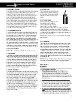
To check the electrode, first do a visual inspection for
cracks or breaks on the ceramic insulator. Also, verify
the mounting bracket is attached properly to the elec-
trode. If either of the above conditions are found, replace
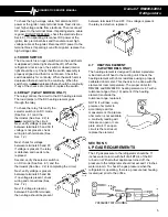
the electrode. Next, check the spark gap. It must be set
at three sixteenths (3/16) of an inch and the tip of
electrode above the slots in the burner.
NOTE: If igniter (See Sec. 4.2) and high voltage cable
(See Sec. 4.4) are good and there is no spark at the tip
of the electrode, REPLACE THE ELECTRODE.
4.4 HIGH VOLTAGE CABLE
NOTE: Be sure switch (See Sec. 4.1) and igniter (See
Sec. 4.2) are good before checking the high voltage
cable and the switch is in the gas mode.
DC Mode
AC Mode
Gas Mode
+Term.Ign.Lamp Term. Block
Thermostat
Thermostat
+Term. on Igniter
7a 6a 5a 4a
2a 1a
AC Mode
Gas Mode
DC Mode
Interior Light Circuit
Door Switch
#86 Term. on
#30 Term.on Relay (+
+Reigniter-Lamp Term.
Interior Light
Circuit
Thermo-
stat
AC Heater
7
6 5 4
2
1
HIGH VOLTAGE
7
4
1
2
6 5
6a
7a
5a 4a
2a 1a
AC Neutral
AC line
HIGH VOLTAGE
3/16"
ELECTRODE
TIP
BURNER


